VCF on VCD: 4a – Stretched Clustering
I shortened the name of the blog-series, to make it a little easier on the eyes.
I mentioned in my previous blog that I was going to build another VCF instance and make that a stretched cluster. However, I thought, technically it should be possible to change the already built VCF02 environment to that. The only thing that I need to do is change the IP-assignment on the NSX-TEP’s.
Please note, this is nót (I repeat NOT) a supported method! If you want to use a VCF stretched cluster, you need to start of with DHCP based TEP-addressing, not change it. Maybe this will become available in the future (I have no knowledge of this!), but for VCF 4.5 and earlier, the only way to create a stretched cluster is by deploying it with DHCP.
Okay, with that statement out of the way, we start on our journey to rebuild VCF02 into a stretched cluster.
I am aiming for the following end-state (from a physical connectivity perspective):
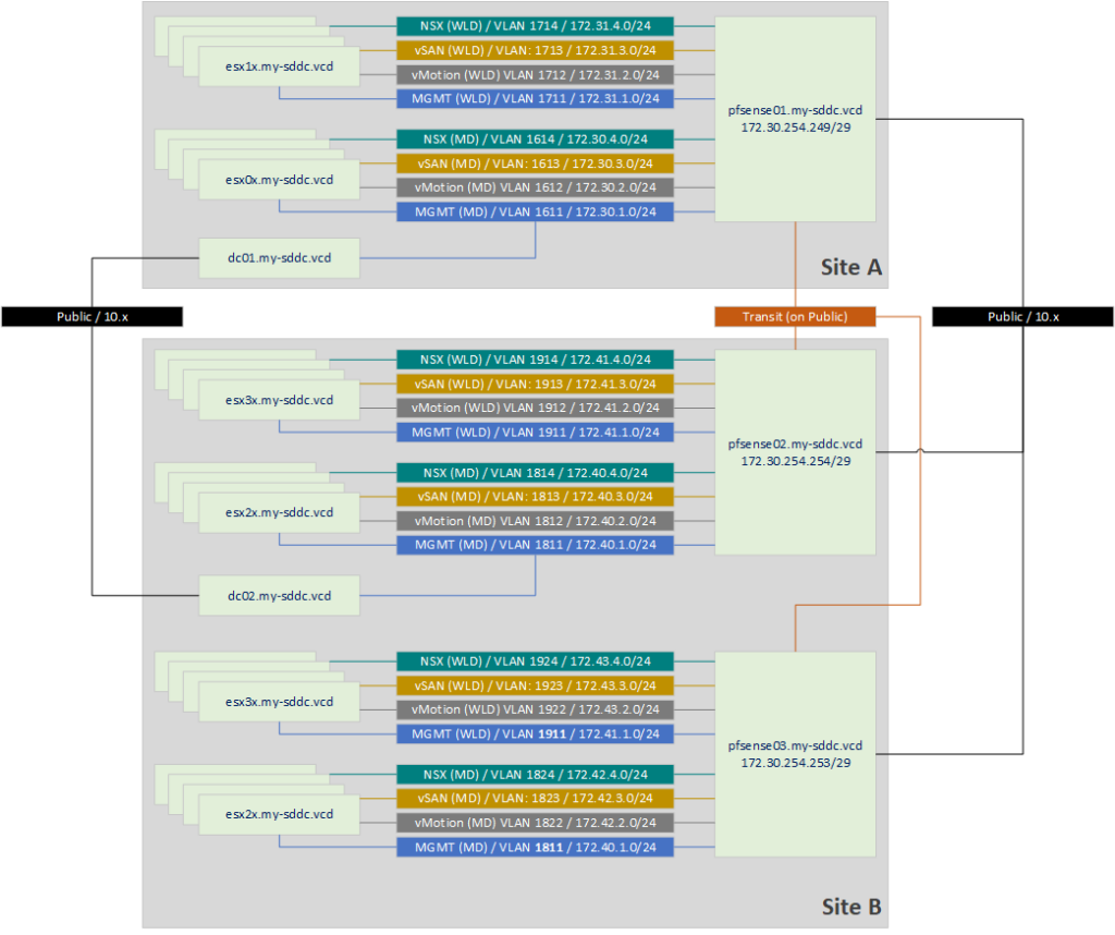
One thing to note here, is that two of the VLANs for the second AZ will be stretched (1811 and 1911). Those are the Management VLANs. That is a requirement to create a stretched VCF cluster. All the requirements can be found here: https://docs.vmware.com/en/VMware-Cloud-Foundation/4.5/vcf-admin/GUID-A56D8E59-A549-4624-BC61-4A92710F9FA1.html. In there we also see some requirements for stretched VLAN’s for the Edge Nodes, but those have not yet been deployed, so that is for a later moment.
For now, we are going to perform the following activities:
- Deploy an extra pfSense appliance
- Create new VLAN’s for AZ2
- Create DHCP Server and DHCP-pool for NSX-TEP VLAN’s
- Change TEP-Assignment on Management Domain from IP Pool to DHCP
- Create a Network Pool for AZ2
- Create four new nodes for the MD (esx25-esx28) and WLD (esx35-esx38)
- Add hosts to DNS
- Commission Hosts
- Create Witness Node
- Stretch Cluster
Deploy an extra pfSense appliance
I decided to copy the existing pfSense02 into pfSense03 and change its configuration. As you can see, I like bullet lists, so here we go:
- Copy the pfSense
- Reset MAC-addresses
- Connect only the WAN interface (vmx2) and set that to DHCP
- Change the IP assignments for VLAN’s 1811 and 1911
- Remove the IP assignments for the VLANs 1812-1814 and 1912-1914
- Change the VLANs 1812-1814 and 1912-1914 into 1822-1824 and 1922-1924
- Assign IP addresses to the VLAN interfaces
- Connect the interfaces to the network
- Set up BGP peering with pfSense01 and pfSense02 (also on the other devices) and check routing tables.
Create DHCP Server and DHCP pool for NSX-TEP VLANs
This I also did on the pfSense appliances. On VLANs 1814, 1914 on pfSense02 and 1824 and 1924 on pfSense03, I created a DHCP scope, with the following settings:
- Enable DHCP Server on the interface
- Range: 172.4x.4.201 – 172.4x.4.250 (this, to not conflict with the existing IP Pools)
- DNS Server: 172.40.1.1
- Domain name: my-sddc.vcd
- Gateway: 172.4x.4.254
And that’s it, the rest I left default.
Change TEP-Assignment on Management Domain from IP Pool to DHCP
Now comes the “tricky” (and unsupported) part. We have to change the TEP assignment from IP Pool to DHCP. For this, I used https://kb.vmware.com/s/article/84194 and more or less used the reserve for steps 10-17 in this article.
On both my NSX environment for the Management Domain (nsx03) and the Workload Domain (nsx04), I performed these actions.
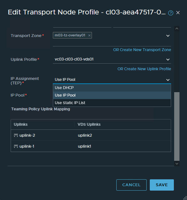
First, we start editing the Transport Node Profile and change the assignment from IP Pool to DHCP:
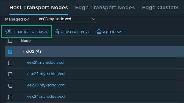
Then we go into System | Fabric | Nodes and select the nodes managed by the correct vCenter Server. Select the Cluster and click “Configure NSX”:
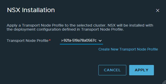
We select the changed Transport Node Profile and click “Apply”:
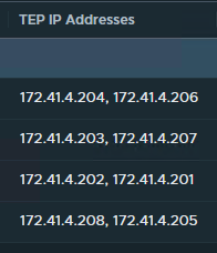
This will change the assignments to the hosts and this should be reflected in the change to the IP Address assignment as well:
Before:

After:
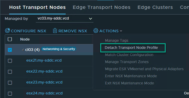
And after this, we detach the Transport Node Profile from the Cluster again:
Create a Network Pool for AZ2
After the NSX configuration is done, we head over to the SDDC Manager for VCF02. We create two Network Pools for AZ2, one for the Management Domain and one for the Workload Domain. The settings are more or less the same (so only the configuration for the Management Domain is shown here).

Create four new nodes for the MD ánd four new nodes for the WLD
This has been described earlier in the series, it’s more of the same:
- Create new hosts (based on an existing host that was not yet used)
- Reset MAC Addresses
- Start VM’s
- Reset the configuration
- Change Password
- Change Network settings (VLAN, IP address, DNS settings)
- Change the VLAN for the “VM Network” portgroup
- Configure NTP
- Change TSM-SSH Service to automatically start
- Configure the host with the correct certificate
- Change tagging on capacity disk
- Reboot host
Add hosts to DNS
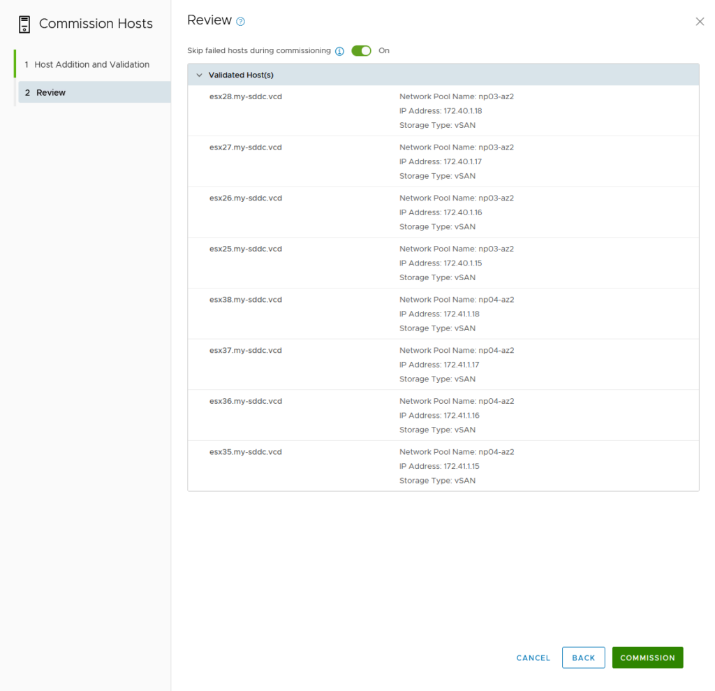
Commission Hosts
Also described earlier: in https://my-sddc.net/creating-a-vcf-lab-on-top-of-vcd-part-2-workload-domain/):
Create Witness Nodes
I will be running the witness nodes on the VCF01 environment, in the Management Domain. Deploying them through an OVA.
Relevant settings:
- Name: esxw01 / 02
- FQDN: esxw01.my-sddc.vcd / esxw02.my-sddc.vcd (added to DNS)
- Medium Size
- Source Networks connected to “cl01-vds01-pg-mgmt” which is the Management network for the cluster
- Network for vSAN Traffic: Management
- IP Address: 172.30.1.91 / 92
- Subnet Mask: 255.255.255.0
- Gateway: 172.30.1.254
- DNS Domain: my-sddc.vcd
- DNS Server:172.30.1.1
- NTP Server: 172.30.1.1

Then we can power on and add both Witness appliances to the VCF02 environment, as stand-alone hosts for each of the DataCenters:
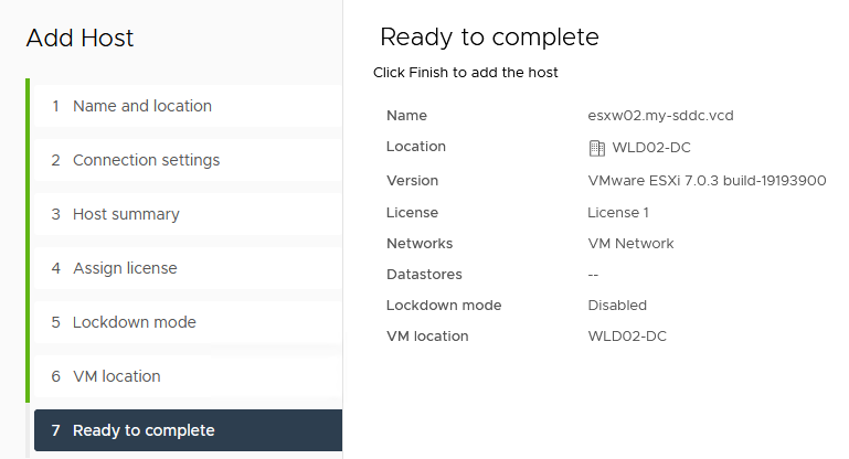
(for information, the VCF01 is “dark mode”, and VCF02 is not, which makes it easy to distinguish between the two).
The last step is to remove the (redundant) network configuration. So we remove vmk1, and the used vSwitch (secondarySwitch). This, is because we will be using the Management vmk (vmk0) for witness traffic.
Stretch Cluster – Management Domain
Now we have everything in place, we can start actually stretching the clusters. For this, we use a JSON-file, which I have created from: https://docs.vmware.com/en/VMware-Cloud-Foundation/4.5/vcf-admin/GUID-CDEEF4C6-7DFC-4EB5-B5F5-3C41230926F9.html.
The values we need to fill in are:
- ESXi host ID’s for all four hosts
- Distributed Switch Name
- Information about the witness appliance
- The NSX Overlay VLAN ID
The ESXi host ID, we get by going to Developer Center > API Explorer in the SDDC Manager interface. There we go to: APIs for managing Hosts | Get /v1hosts
We fill in the Parameter “status” and fill in UNASSIGNED_USEABLE:
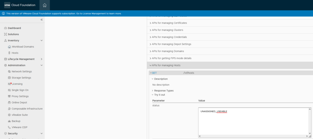
and click on “Execute” (scroll down for it). Which will result in:
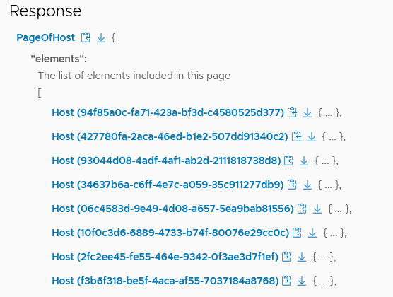
We have to select the correct hosts (esx25-28), so we need to click on the hosts to see which of the ID’s are these hosts (it’s not the first four, in this case).
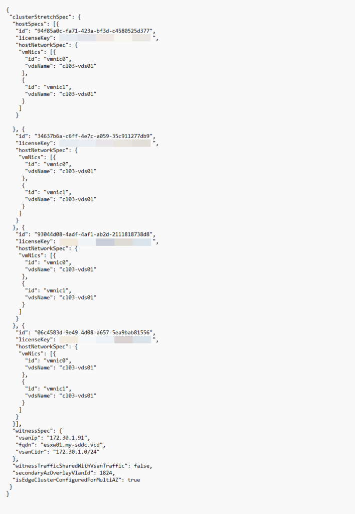
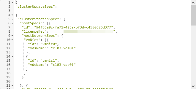
After all the hosts have been found, I created the following .json file:
This we will validate. Again we go to the Developer Center > API Explorer. This time, we go to APIs for managing Hosts | Get /v1/clusters and click “Execute”. This will give us the correct ID for the cluster we are extending:
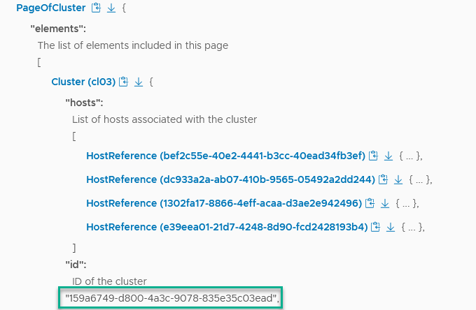
With this information, we go to POST /v1/clusters/159a6749-d800-4a3c-9078-835e35c03ead/validations. We fill in our .json file in the “clusterUpdateSpec” box, preceded by:
{
"clusterUpdateSpec":
Then, the created .json file and finish with
}
So, that becomes:
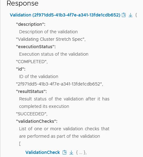
(just a part of the complete .json). And we click “Execute” and accept the warning that this will possibly lead to changes to the live environment.
The validation succeeds:
With the validation completed, we move to: PATCH /v1/clusters/{id}. Put in the correct cluster-id (159a6749-d800-4a3c-9078-835e35c03ead) and fill the clusterUpdateSpec box, with the created .json:
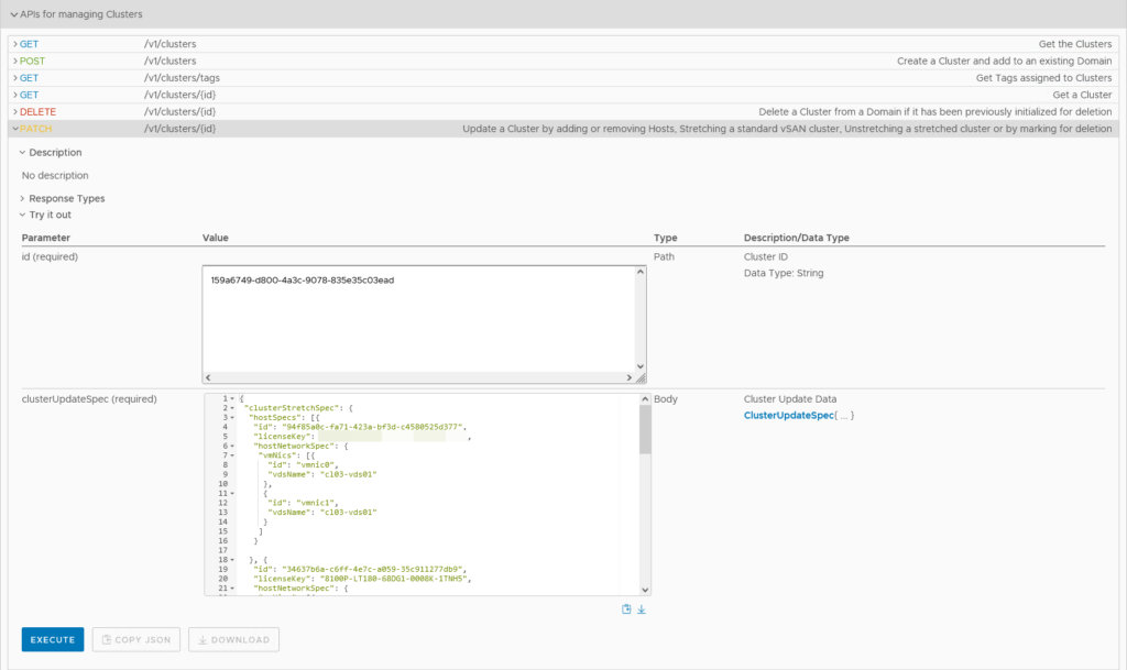
(without the preceding and trailing parts we used in the validation). And click “Execute”
(before I did this, I created a snapshot of the vApp, just in case).
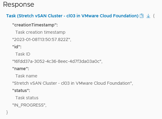
Again, we accept the warning, and then the stretching is underway:
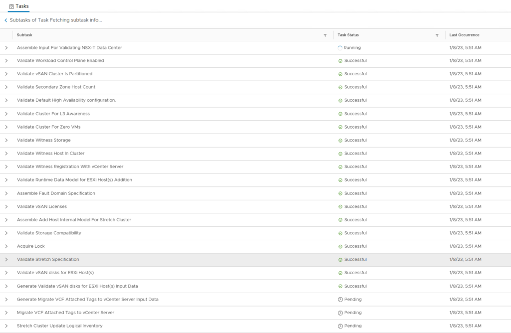
Again, the need to help the vDS configuration and the disk group creation along.
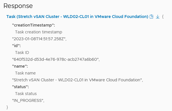
And after a little over half an hour:

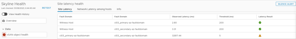
It will take some time to sync all data. And in the meantime, we get some errors on vSAN (the network connectivity is not “Enterprise” grade, as you can imagine, with pfSense appliances in between):
After this has steadied, we do the second part, for the WLD, with the same steps:
During this stretching, I got the following error:
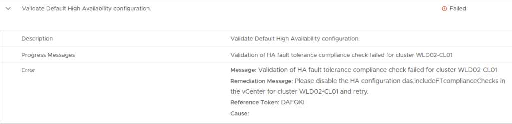
When I looked at this Advanced Setting on the cluster, it is set to true. The same setting for the Management Domain is set to false and on the other VCF environment, it’s the same (MD=false, WLD=true). I set it to “false” and move on (then the check succeeds).
And after that finishes (again, helping it along at both the vDS and Disk Group stage):

we have the following topology, from a VCD/VCF perspective:
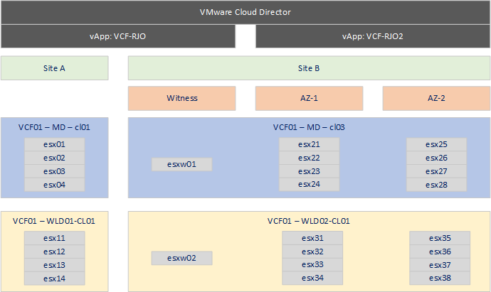
So, a Sunday well spent, rearchitecting a single-site VCF environment into a stretched environment :).