Routing with NSX-T (part 2)
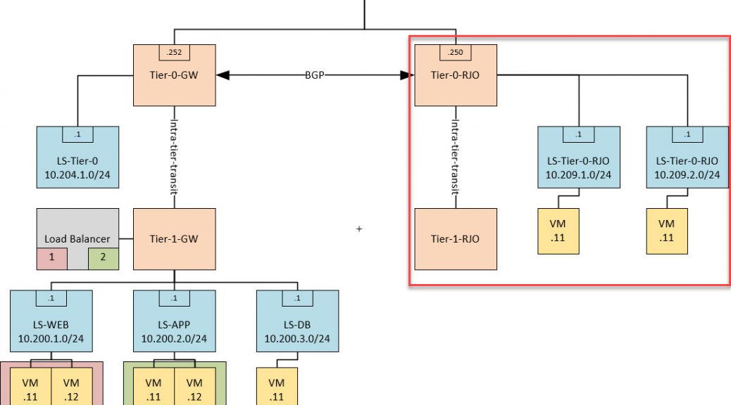
So after the theory, it is time to create some routed networks. In order to do this, I created a design on what I want to accomplish. Part of the design is already in place, but for this blog I have created the part which is visible in the red square:
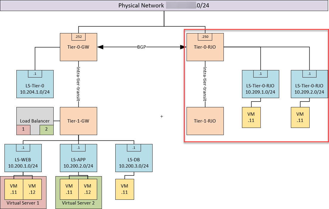
So we already have a tier-0 gateway, connected to a tier-1 gateway, which is connected to several segments. The existing tier-1 is also used as a load balancer for my three-tier-app. In the picture you can see the red and green virtual server, which are running on the Load Balancer, connected to the tier-1 gateway.
I also connected a segment to the tier-0 gateway, just to see how routing between tiers would function and as might be expected, routing is done within the hypervisor.
So time to create the new parts within the design.
First we have to create a new Edge Node. This is necessary because my existing edge node is not capable of running multiple tier-0 gateways with uplinks to the physical network. So when creating an Edge Node, it is important to have the following information handy:
- Transport Zone the edge node is going to be connected to
- N-VDS’s used to connect to the transport zones
- Connectivity to the physical network (in my case, through the use of dPG’s).
- FQDN / IP-address / Port Group for management of the edge node
After all this information is gathered, it is time to create an edge node:


After the edge node is created and running, it can be added to an Edge Node Cluster (no picture taken, this is self-explanatory).
When the edge node cluster is available, we can deploy our tier-0 gateway:

And after that we can create an interface, which can be used as an uplink for this tier-0 to the physical network (last octet being .250).
At this stage, the tier-0 gateway is available and new segments can be created and connected to the tier-0. As can be seen in the picture, I created two segments, connected to Tier-0-RJO (one showing):

As you can see, this segment is connected to Tier-0-RJO. I have added an IP-address and subnet to the segment, which will automatically create the corresponding interface to the tier-0 gateway.

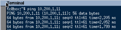
This way I have created two segments, with the subnets 10.209.1.0/24 and 10.209.2.0/24. Both connected to the tier-0 and as such virtual machines deployed to these two segments should be able to communicate with each other:

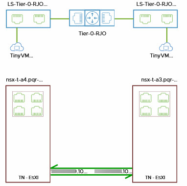
Within NSX (V or T) there is a tool called TraceFlow which allows us to see a little further than just a response to a ping request. So to see how traffic flows from one virtual machine to the other, I used this tool.
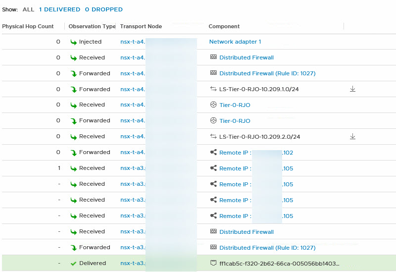
It displays the path the packet takes:
and every step along the way:
So this basically is everything in the red square…
However, I also want to see if it is possible to communicate from this part of the network, to the part on the right. I want to use my web-server, which is connected to the segment LS-WEB.
If I try this without any further communication, it (of course) fails. There is no route-information being exchanged between both tier-0’s and also no static routes have been configured.
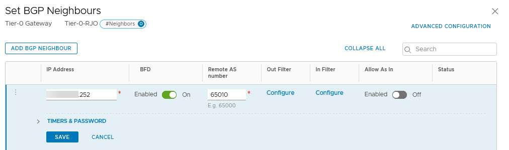
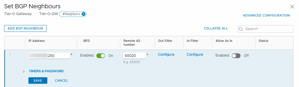
In order to get the communication working, I configured BGP. I have set up BGP on both tier-0’s, where I use different AS’s (65010 for Tier-0-GW and 65020 for Tier-0-RJO).
Then connect both tier-0’s as each others neighbor:
After that, I selected which routes need to be advertised between the tier-0’s (by default nothing is exchanged):
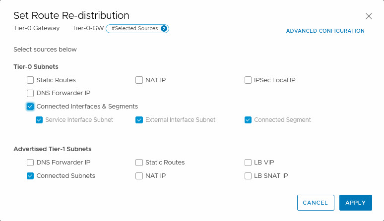
and after that, Bob’s your uncle:
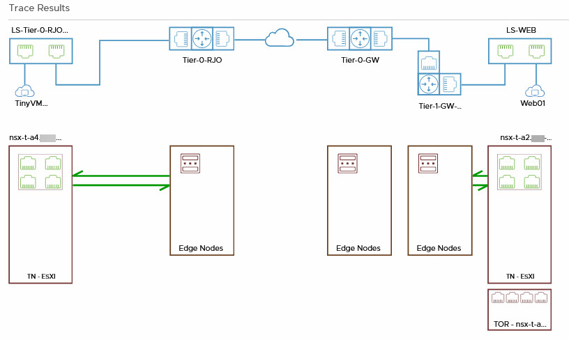
Just to see how the path between the two virtual machines is, I used TraceFlow one more time, pretty impressive flow, for such a small environment 😉 :
So that is routing within NSX-T. Next up, Load Balancing…
11 thoughts on “Routing with NSX-T (part 2)”
BGP Peering between T0 (SR) is that supported now, my understanding is that is the unsupported configuration as of the current stable releases.
Must say that I do not know that. Do you have a reference to this? However, since I don’t control the physical layer in this environment, I can’t do BGP that way.
I did find this site: https://docs.pivotal.io/runtimes/pks/1-2/nsxt-multi-t0.html#bgp where there is peering between multiple T0’s, for a PKS deployment.
(Edit):
Asked around on the vExpert forum and have confirmed that it is a supported topology, used at production sites currently.
Thank you, VMware for following up. I guess some of this stuff is not publicly available; hard to tell what is supported in any given release of nsx-t. It is been developed so fast that everything is changing all the time. nsx-t 2.4 is beast with converged appliances and clustering, and some things moving to policy manager….just hard to keep up with nsx-t.
Keep up the good work and building the fundamentals.
Hi. I want to know, if tier-1 logical router is distributed router or can be only service router (centralized on edge node) like tier-0 router?
Hi, Logical Routers (T0 and T1) can have a distributed and a service component. When deploying a T1, you can choose not to put it on an edge node. That way it won’t use the service component, but as far as I’m aware, the distributed component is always deployed.
But when you put a T1 on an edge cluster and only use a T1 for services, it won’t use the distributed component.
Thank you. So what I see, logical router at T1 or T0 could be deployed either distributed or service router (T1 normally as distributed as it is first hop and T0 is service router). Do you know what is the use case to deploy them as both distributed and service router? thx
Hi Kashif, all T0 and T1 logical router have both a distributed and a service component. The distributed component will do the east-west routing (this can be both T1 and T0 or even a combination of T1’s and (one) T0). The service component is used when you deploy centralized services on the T0 or T1. Like North-South routing (only on T0), Load Balancing (only on T1 at the moment), NAT or Edge Firewalling (so not the distributed firewall, this is done on the host).
The service router instances of all T0’s and T1’s are run on edge nodes, the distributed router instances are run on the transport nodes (eg. hosts).
Thank you. Great explanation !