VCF on VCD: 1 – Preparation and Management Domain
At VMware Explore, I got an interesting question from a customer. They are a VCPP partner and are leveraging VMware Cloud Director to service their customers. They were asking if it is possible to create a (nested) VCF environment on top of VCD. I said, yes, that should be possible, the HOL is an excellent example of where this is done, but I saw little information on the exact way how to build this configuration.
At VMware we, as TAM’s, have the possibility to create our own lab environments. For this we use a VMware Cloud Director environment, dedicated for TAM’s. So I thought it would be interesting to see how to go about building a VCF lab on top of VCD.
I will be starting from scratch and will create a VCF 4.5 environment, with all the necessary prerequisites to create and run this, from zero. For this, I created an empty vApp within VCD, called:
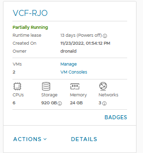
And, of course, we also need a little bit of a design. This might (will) change over time, but let’s start small. First, we are building:
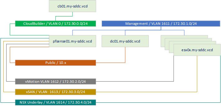
So, one DC, that will contain network services, Domain Controller functionality and be a stepping stone to get to the environment. One Cloud Builder VM, that will help us deploy our VCF environment and a couple of ESXi servers that will contain this VCF environment.
I created the dc01 and promoted it to become both a Domain Controller and DNS server for the rest of the environment. I can access the dc through the “Public” Network, which is (for me) reachable internally over VPN.
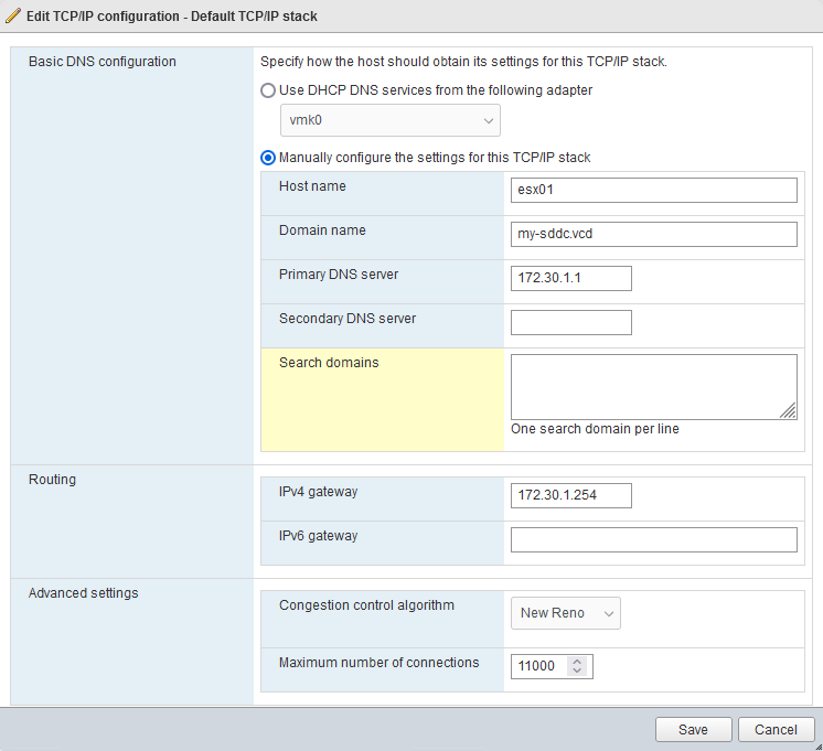
As a Domain Name, I chose “my-sddc.vcd” (as I already use my-sddc.local in my local lab 🙂 and vcd of course, related to VMware Cloud Director)
After installing the Domain Controller (and configuring it for all the other roles it will get), I deployed the Cloud Builder Appliance. There was already a template in the environment that contained Cloud Builder 4.5 and I deployed a new VM from this template (but installing a freshly downloaded Cloud Builder VM would be the same starting point, but it is rather large, so I took the shortcut of the template).
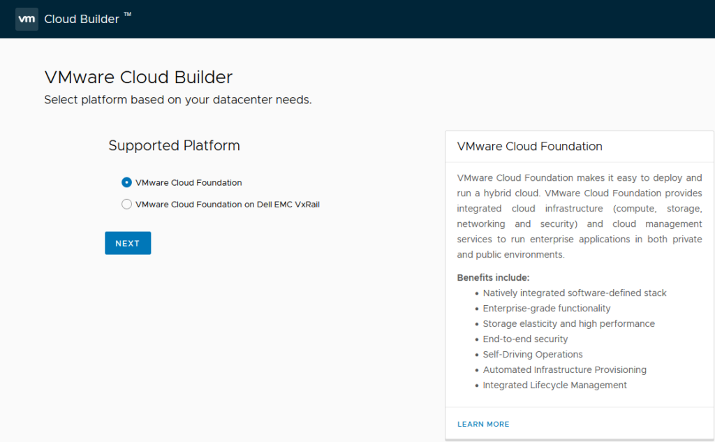
After starting it, it gives me a nice overview of what I need to do:
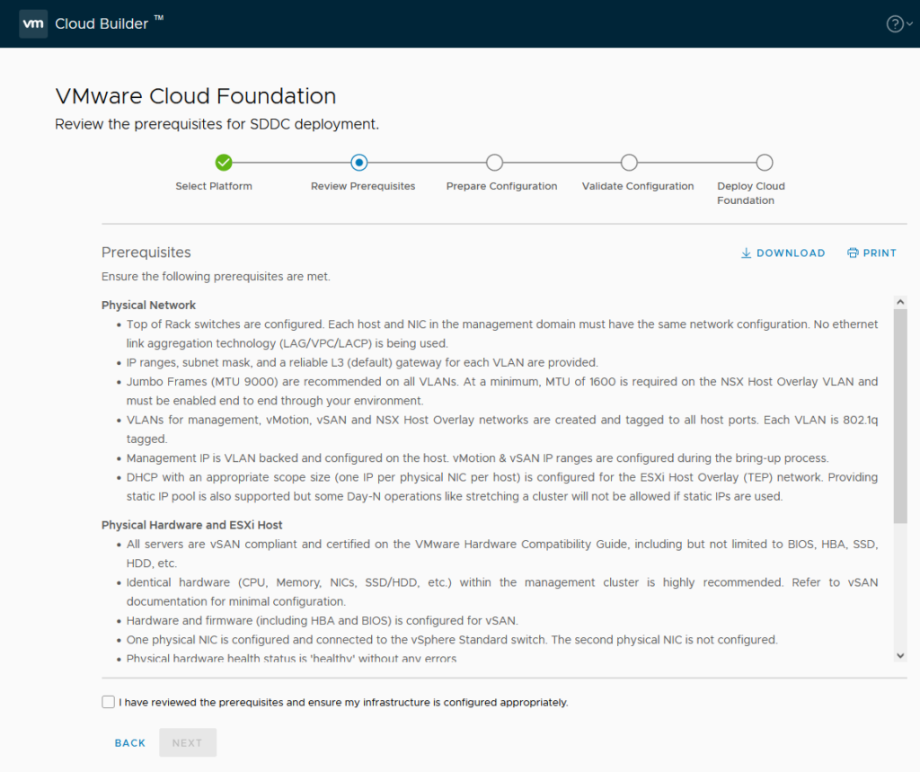
So next, it is time to create some prerequisites, which are presented on the next page:
First up, we create some new (nested) ESXi servers. For this I am using the following configuration:
- 1 socket 16 cores CPU
- 128 GB Memory
(in hindsight, this is too small. I would opt for 16 x cpu and 128 GB of memory. I will change it later in the process, during the bring up, but if you start from scratch, use the larger size if you have the option).
- 16 GB Storage for OS
- 100 GB Storage to be used as a cache device –> Bus type: NVME
- 1000 GB Storage to be used as a capacity device –> Bus type: NVME
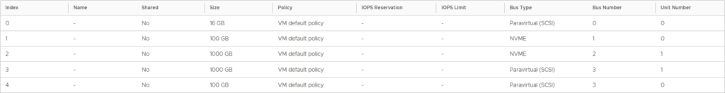
It is important to set the largest of the two as a capacity device (described further on).
So I start with the configuration as mentioned and after the deployment has completed, move to the configuration with only the NVME devices (see the last part of this article).
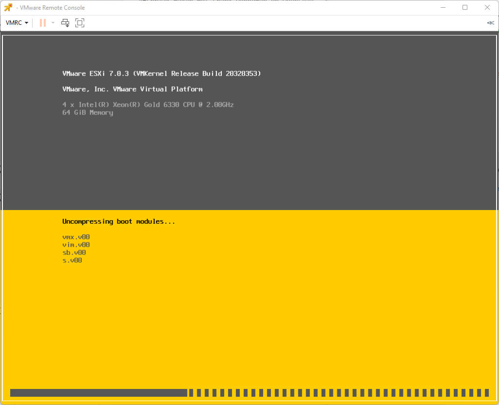
I boot the VM with the .iso attached, to install the correct version of ESXi, related to VCF 4.5 (find out the correct version in the Release Notes), which is 7.0 Update 3g, build 20328353.
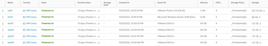
After installing this host, I copied it another 3 times, so I have 4 hosts in total:
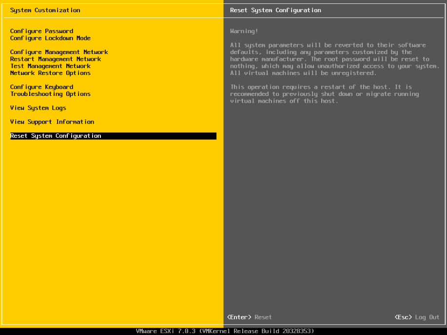
Important to do a reset of the configuration, because ESXi will by default reuse the same (virtual) vmk mac-address (based on the initial host’s physical mac-address) if you don’t.
So log on to each host and in the DCUI use “Reset Configuration”:
Now, it becomes important to configure both the hosts and the environment in a way that VCF can be deployed. That means doing the following activities:
- Configure Networking (allow Guest VLAN tagging)
- Configure VLAN on the ESXi hosts
- Configure Routing
- Configure the hosts with the correct certificate
- Change setting “CapacityFlash” on capacity NVME device
- Configure DNS (Forward and Reverse)
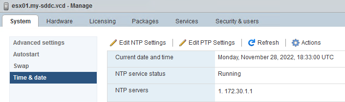
- Configure NTP
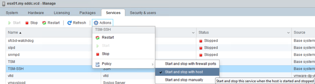
- TSM SSH Service to start and stop with host
Configure Networking (allow Guest VLAN tagging)
The “Allow Guest VLAN Tagging” setting on the Network within the vApp will allow all VLAN’s to be utilized. Basically it means that VLAN 4095 is attached to the port group. So I can use all the VLAN’s I want, in the sheet I will be using to deploy VCF:
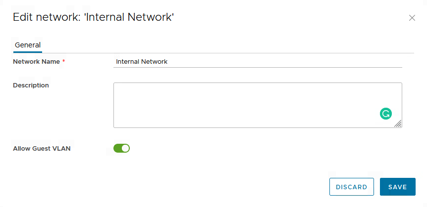
This also allows me to connect a router to the segment and use it to route between all the VLAN’s that VCF will be using.
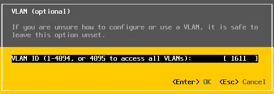
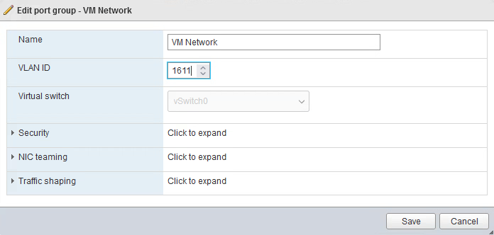
Configure VLAN on ESXi hosts
Since the hosts will be configured using a VLAN (and since, with the previous step, VLAN’s are allowed throughout the Internal Network), I configure the hosts to use VLAN: 1611:
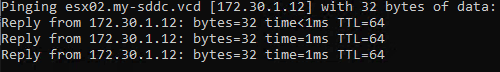
And also configure that on the Windows DC, for the internal network:
and after that, connectivity is there:
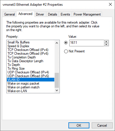
After configuring the VLAN on the Management Interface, I also need to configure it on the VM Network Port group, for all the hosts:
Configure Routing
Because we need internal connectivity and a gateway to connect to, within the internal network I am going to deploy a routing VM. In the case of this environment, I am going to create a pfSense VM. I deploy the pfSense VM and configure it to route between the different VLAN’s I will be using within the environment:
The VM will have one network connection to the public network and one connection to “Internal Network”. Due to the VLAN setting I made in the previous step, I can create all necessary VLAN-interfaces on the router, to create my own little (Virtual) DataCenter.
Look at the Firewall settings within pfSense, since it disallowed some traffic between my Cloud Builder network and the Management network (ping did not work), so make sure you create the right “allow” rules to make sure traffic flows as needed.
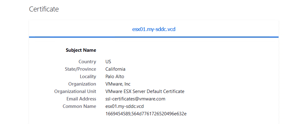
Configure the hosts with the correct certificate
By default, the hosts will contain a self-signed certificate that holds the “wrong” name:
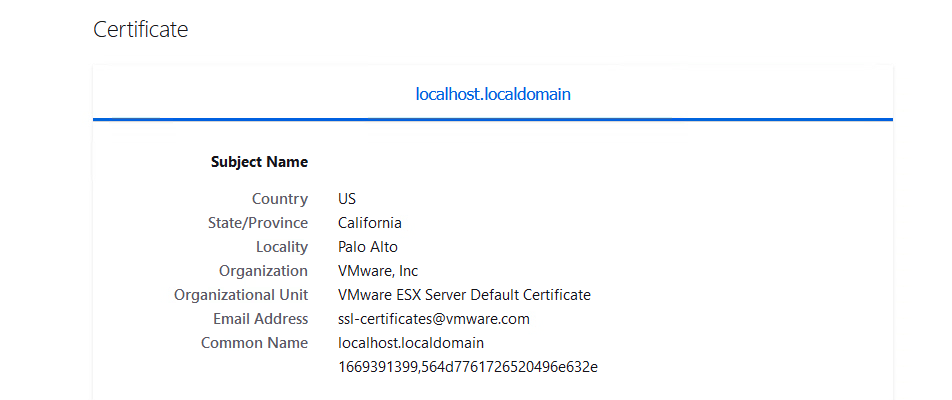
We need to change this, so the correct “Common Name” is reflected in the certificate.
For this, we can use the command: /sbin/generate-certificates and then reboot the hosts. Then the certificate shown will be the correct common name:
Change setting “CapacityFlash” on capacity NVME device
On the Capacity disk set “IsCapacityFlash” settings to 1:
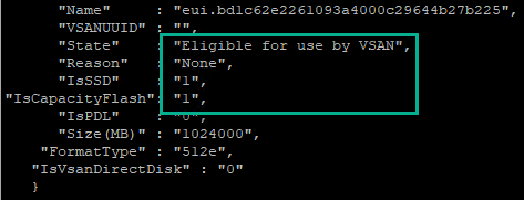
This will make sure that the disk groups can be created on the hosts. This can be done by finding the correct “Name”, through the command vdq -q and then, for the correct disk, use the command:
esxcli vsan storage tag add -d <device name> -t capacityFlash
After DNS and NTP have been set up:
the TSM SSH Service is started ánd set to start and stop with the host:
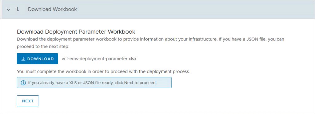
I can download and start filling out the VCF Sheet:
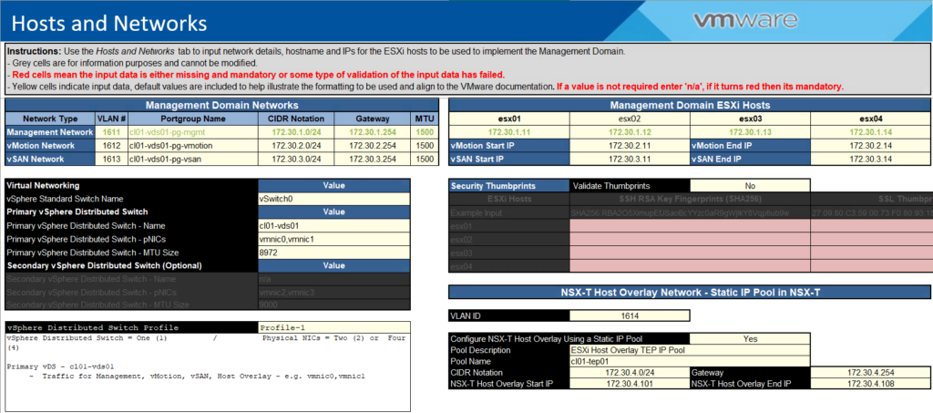
I am going to maintain the VLAN-ID’s but will change the IP addresses to my own design. I also chose not to validate the Thumbprints, but in a production deployment that is of course something you need to do:
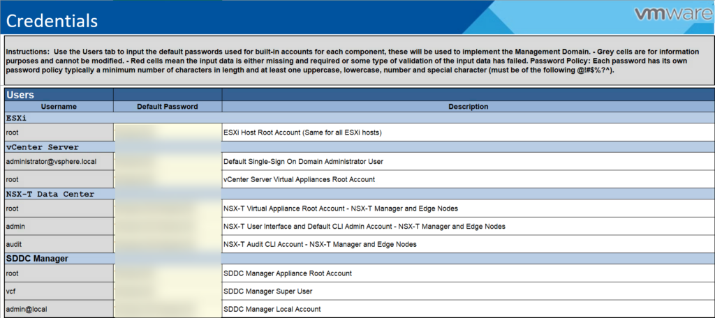
Credentials:
Hosts and Networks:
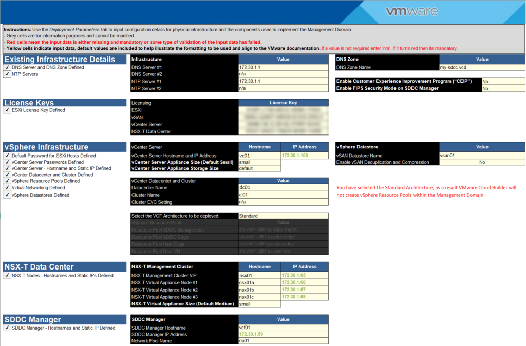
Deploy Parameters:
Making sure all names and addresses are of course neatly put into DNS, both forward and reverse.
After this is all done, it is time to put the pedal to the metal, and insert the Sheet into the Cloud Builder Appliance:
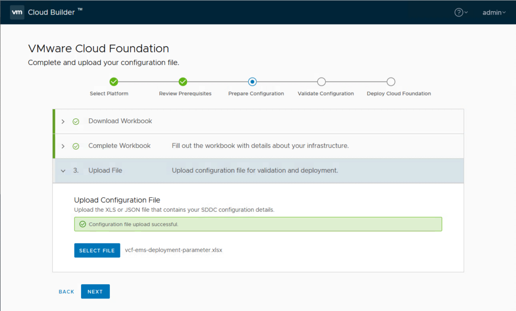
and validate the configuration:
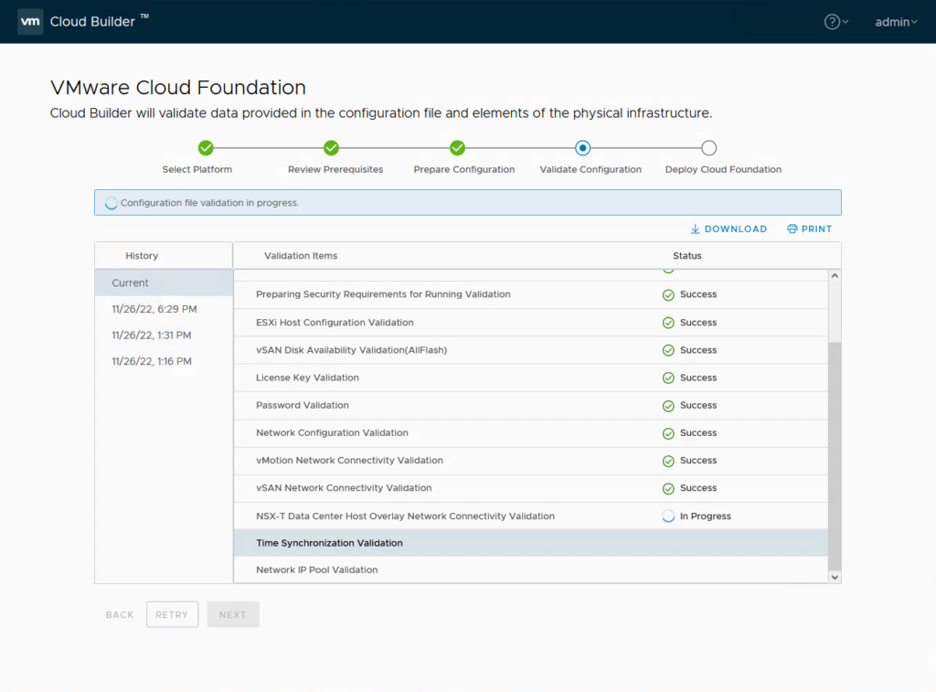
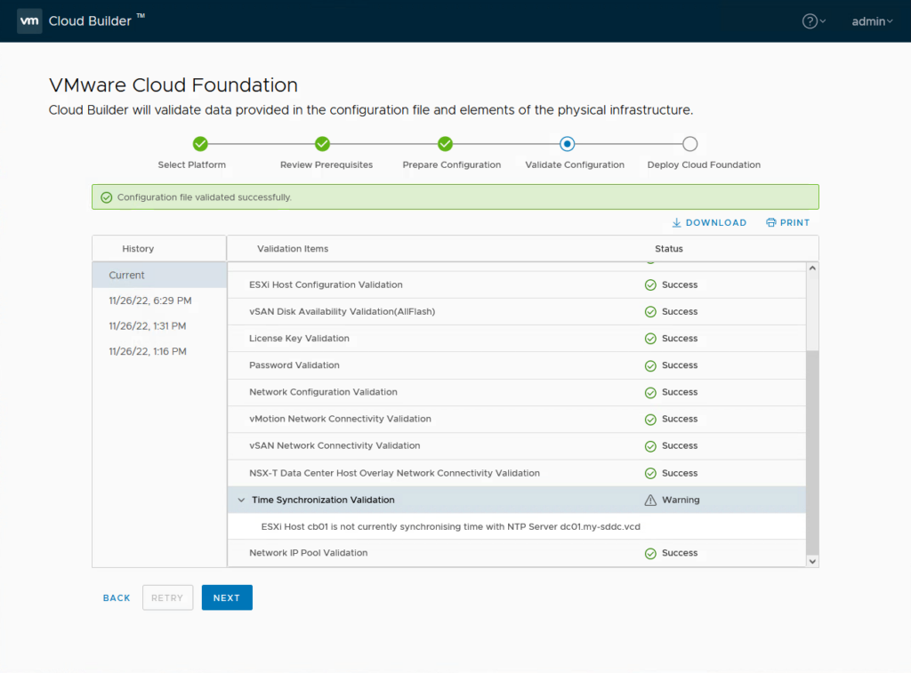
And when the validation is completed:
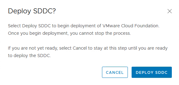
we can start the actual deployment (but first, I created a snapshot of the vApp, just in case):
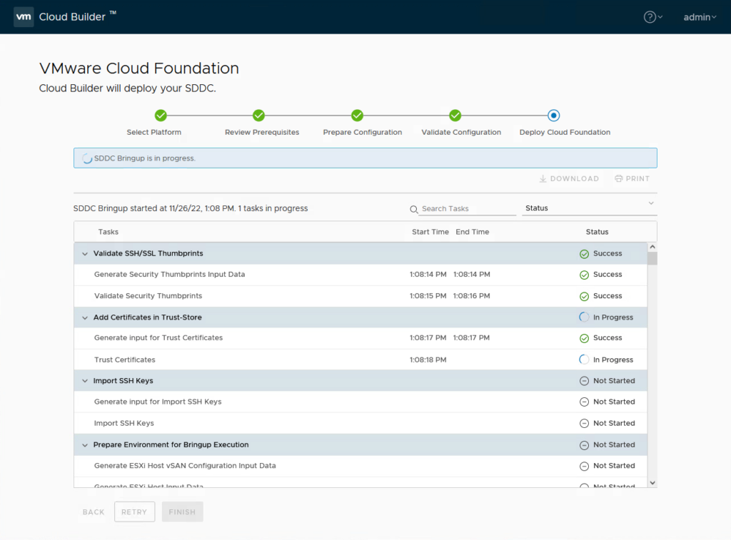
And then we wait (I started this on a Saturday night (although in the US, where my client is running, it’s only early afternoon ;))), so I’ll see the result tomorrow morning).
It failed a couple of times for several reasons, but otherwise we won’t learn, so let me write down the issues and the way I went around them. Most have to do with the environment being nested and performance being not really production ready.
- Network configuration
- vSAN Configuration
- NSX Deployment
- Deployment of SDDC Manager
Network configuration
So, first time, it failed. It failed because the vmk0 of the esx02 was not able to be migrated to the Distributed Switch:
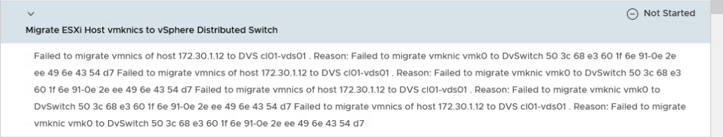
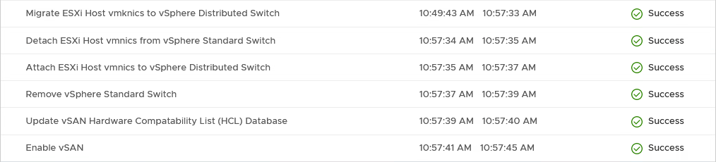
The vmk0 of the esx01 had migrated but was no longer reachable from the DC01. However, since the deployed vc01 (vCenter Server) was running on the esx01, I could still manage the configuration. What I needed to do was both change the dPG to only use vmnic0 (uplink1) and migrate both the vmk0 ánd the vmnic0 at the same time. After this, the process went through:
vSAN Configuration
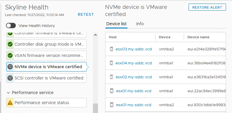
I also had to help the vSAN configuration a little, with Silencing the alerts around the certification of the NVME and SCSI controllers:
Another vSAN thing that might go wrong, is creating the disk groups for the other hosts (2, 3 and 4). I am not sure why, but after manually creating them (without a problem), and retrying, it moves forward.
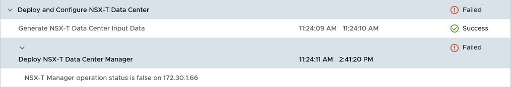
NSX Deployment:
Next issue I ran into, was the deployment of NSX. Because it is a nested environment, the NSX appliances deploy slowly and are too slow before they are fully functional. This leads to them being deleted and redeployed again and again (until CloudBuilder deems it enough and stops):
The way to address this (at least, that is what I have done) is wait for the VM’s to be powered on and then pause the Cloud Builder VM until the NSX configuration has completed (thanks to Shashank Mohan, from https://communities.vmware.com/t5/VMware-Cloud-Foundation/VCF-4-0-stuck-at-quot-Deploy-and-Configure-NSX-T-Data-Center/m-p/2828328/highlight/true#M649.
After pausing the Cloud Builder, giving NSX the time to do it’s thing and restarting, the process continues:
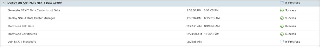
It does take a long time to deploy and configure the whole NSX part, so be patient. Take a look at the status of the NSX Managers, but don’t force anything while the process is running.
After doing that and “Retrying” the deployment, everything completes:
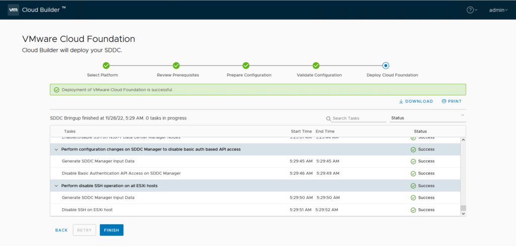
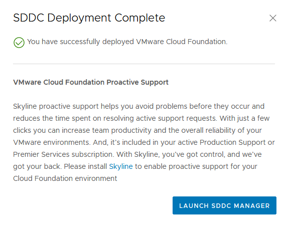
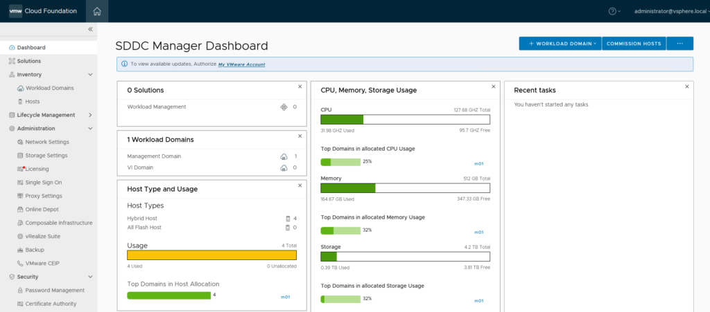
And after clicking “Finish” I can look at the SDDC Manager:
Now on to some cleaning up.
- Remove the Cloud Builder VM
The Cloud Builder VM can be removed from the VCD environment.
Next step: Deploying a first Workload Domain. (that’s part 2).
3 thoughts on “VCF on VCD: 1 – Preparation and Management Domain”