Load Balancing with NSX-T – Part 1
So after I looked at the installation, the fabric and routing and switching, it is time to take a look at the higher level networking functions within NSX-T, like Load Balancing. The functionality itself has not changed very much since NSX-T (compared to V), but the way that it is consumed is different.
As described in an earlier blog (Routing with NSX-T (part 1)), NSX-T uses multiple entities within it’s fabric. Two of which being tier-0 and tier-1 gateways and load balancing can only exist on a tier-1 gateway. So when you use Load Balancing within NSX-T you have to deploy both tier-0 and tier-1 components.
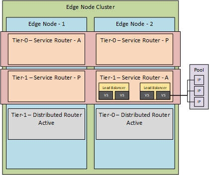
As described in the aforementioned blog, the tier-0 and tier-1 gateways are running within an Edge Node (which can be either virtual or physical). The Edge Node is assigned through the use of an Edge Node Cluster, so it basically looks something like this:
(almost ran out of colors there ;)).
So when we look at it hierarchically, we have an Edge Node Cluster which is made up of one or more Edge Nodes. Edge Nodes can contain one or more tier-0 or tier-1 Logical Routers, which are comprised out of a Distributed component and a Service component. A Service Router can be used to run a Load Balancer in it, which can contain one or multiple Virtual Servers.
And the last step is that each virtual server can use a server pool, which consists of one or more targets (in the form of an IP-address).
Mode
Load Balancing within NSX-T can be done in two ways:
- One-Arm Load Balancing
- Inline Load Balancing
The difference between the two is described in the NSX-T administration guide in a better way than I can, so I’ll blatantly copy this from: NSX-T 2.4 Admin Guide (including the pictures):
One-Arm Load Balancer
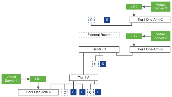
“In one-arm mode, the load balancer is not in the traffic path between the client and the server. In this mode, the client and the server can be anywhere. The load balancer performs Source NAT (SNAT) to force return traffic from the server destined to the client to go through the load balancer. This topology requires virtual server SNAT to be enabled.
When the load balancer receives the client traffic to the virtual IP address, the load balancer selects a server pool member and forwards the client traffic to it. In the one-arm mode, the load balancer replaces the client IP address with the load balancer IP address so that the server response is always sent to the load balancer and the load balancer forwards the response to the client.
Inline Load Balancer
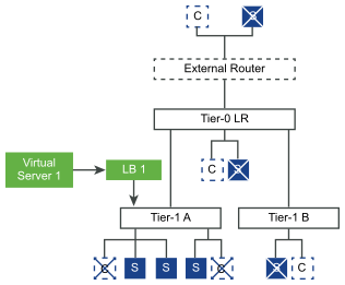
In the inline mode, the load balancer is in the traffic path between the client and the server. Clients and servers must not be connected to the same tier-1 logical router. This topology does not require virtual server SNAT. “
(end of excerpt)
We will deploy both modes, but in this blog, we are only doing the one-arm.
So we’ll start with creating a Server Pool, containing a couple of web servers. For this, I’ll use two LAMP-stack based virtual machines, with Apache enabled and a very basic website, which will show me to which server I am connecting.
So building on the environment that I already have in place, I am going to deploy the virtual machines on the LS-Web segment. So they should be reachable within the network. And since this is the “one-arm” mode, I can place my targets anywhere I want, as long as the ip-addresses I configure in the server pool, are reachable by the load balancer.
Just for reference, the topology that we are working on:
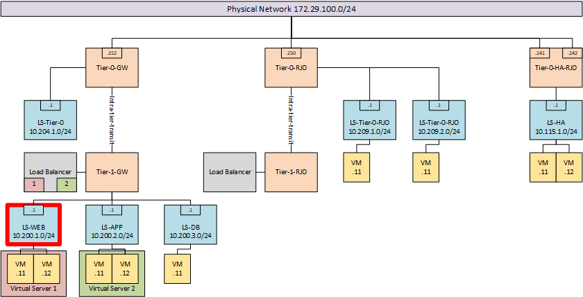
and the segment where the virtual machines are going to be deployed, which is LS-WEB. For these virtual machines I am using the IP-addresses 10.200.1.101 and 10.200.1.102.
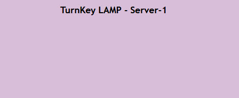
Only difference between the two virtual machines, is the background color within their web-page and the name of the server. The first machine shows:
And the second one shows:
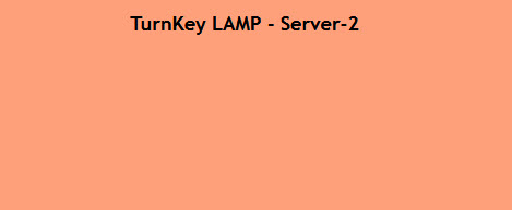
(yes, I do like playing around with colors ;)).
So within NSX-T, we can now create a server pool, consisting of the IP-address used by these virtual machines:
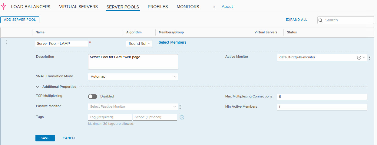
One thing to mention here is the “Active Monitor”. That is the method that the load balancer is using to determine the status of the members. In this case, the “default-http-lb-monitor” is selected. That will perform a simple http-get and when it gets a response, it will assume the server is available. But you can do a lot of more advanced monitoring here.
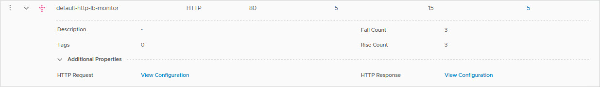
Here you can see the default monitor:
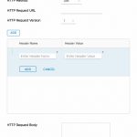
and the additional HTTP Request and HTTP Responses you can add to a monitor (not the default of course):

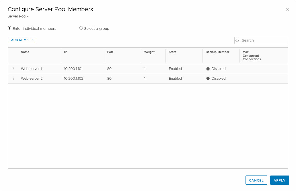
When creating the server pool, we can also add members to the pool. In order to do that, we click the “Select Members” link, which leads us to a page where we can add members:
Before we can create a Virtual Server, we first have to create a Load Balancer and connect that to a tier-1 gateway. What we’ll do is create a new tier-1 gateway and connect it to the existing tier-0 gateway named “Tier-0-GW”. This way, all the routing configuration is in place.
So we create a tier-1 gateway, connected to “Tier-0-GW”:
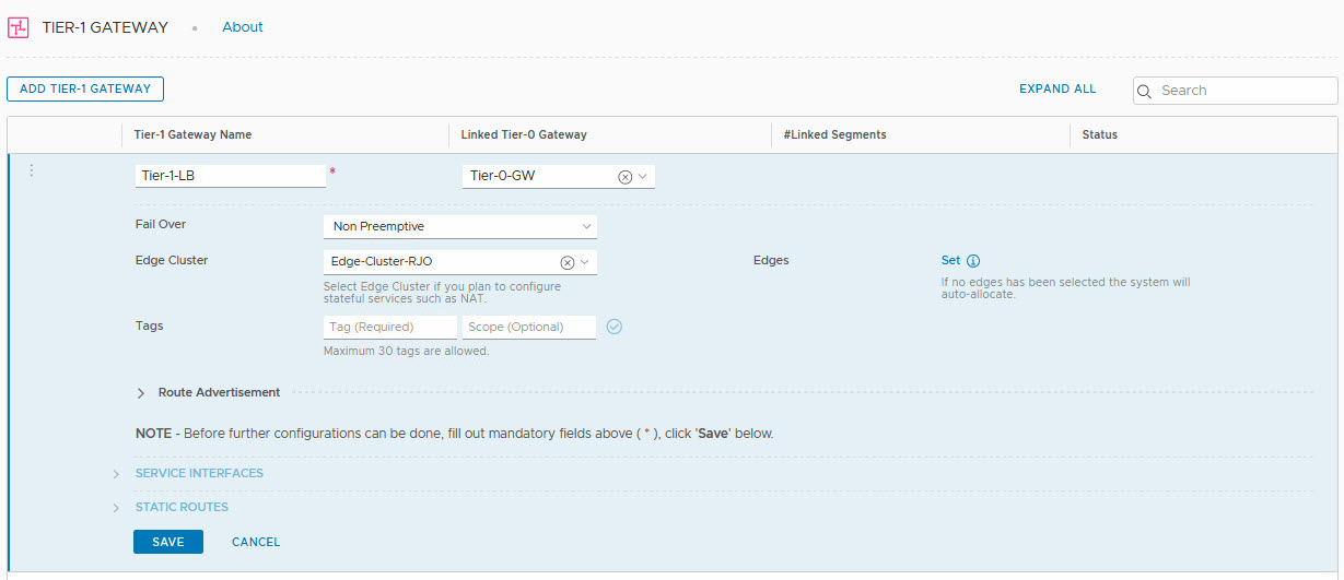
The tier-1 gateway is going to run on the edge node cluster: “Edge Cluster – RJO” and after that, we can select the edge nodes that we want to use for the load balancer, by clicking “Set”:
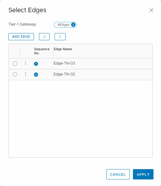
This is not necessary. If you don’t select the nodes, it will auto-select the edge nodes to run on.
Another noteworthy part in the configuration of the load balancer, is the advertisement of the addresses:
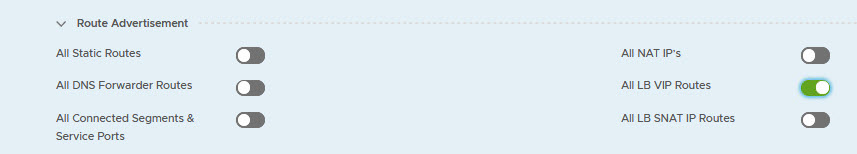
We select “All LB VIP Routes” and that way we know that the addresses that we are going to use with the load balancer, will be known throughout the network. In our example, we will use a totally different addressing scheme, just to show the route advertisement.
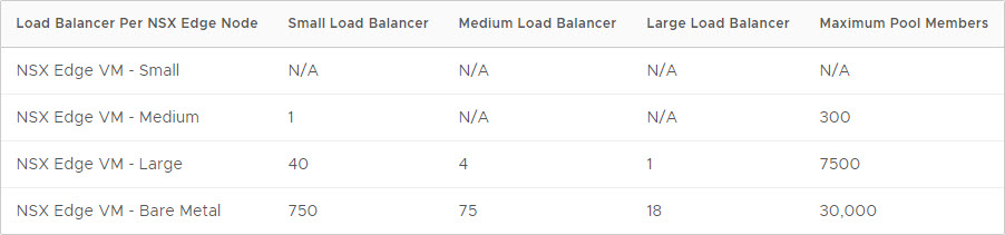
Now that the tier-1 gateway is created, we can create a load balancer. The number of load balancers that can be created, is dependent on the size of the edge nodes:
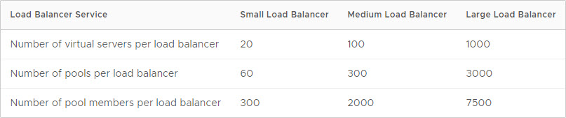
and the number of virtual servers that one load balancer can host, is dependent on the size of the load balancer:
In our lab-environment, there are no issues here, as long as we select an edge node which is at least “medium” sized.
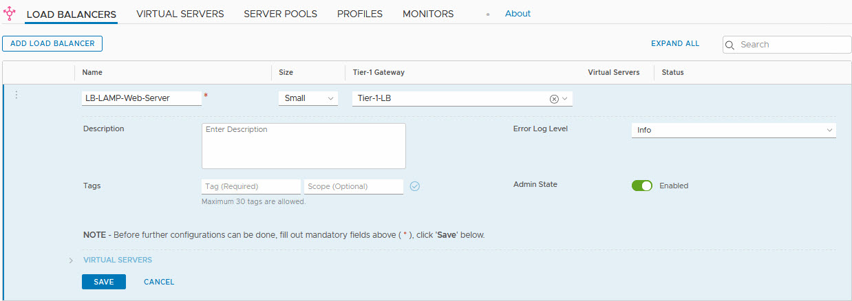
So time to (finally) create the load balancer:
And after the creation (press save), we can select one or more virtual servers:
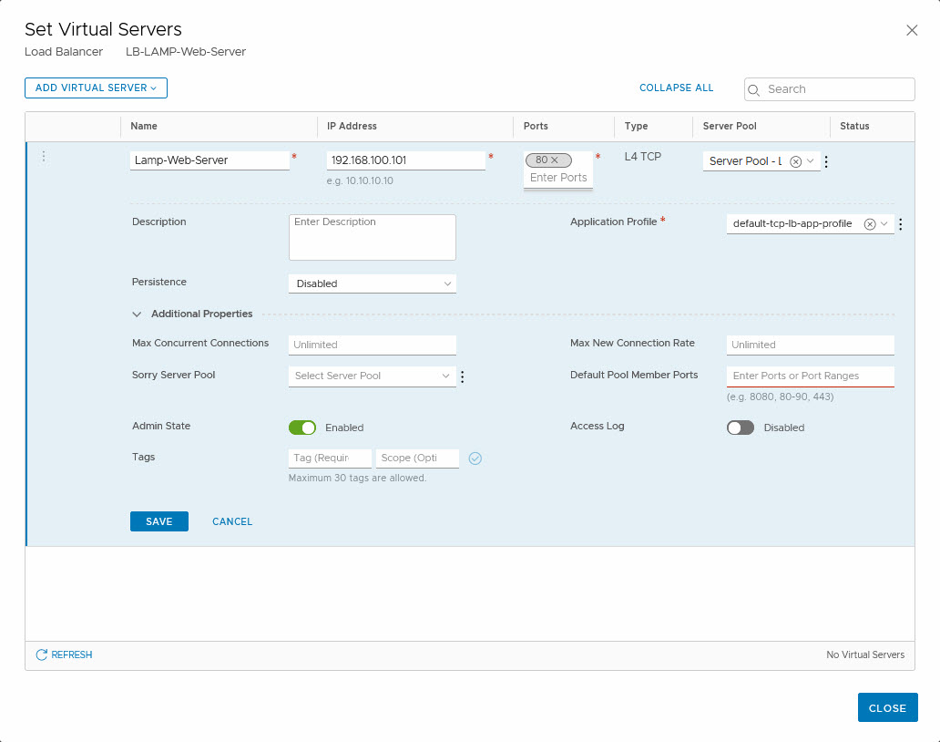
As you can see, we have used an IP-address in a completely different subnet. We have selected the Server Pool we created earlier (although the name is not fully visible, trust me on this one ;)).
We select an Application Profile in which is defined how the application will behave. One option we have here, is to insert a header when the website is running on a server with multiple web-servers, that are separated by a host header.
I do like the “Sorry Server Pool”, which will be used when the Virtual Server is unavailable or maxed out. This is a functionality that NSX-V doesn’t have. We can also define how persistence is managed. With a Layer-4-TCP Virtual Server (which we are creating) this is limited to Source IP, but when we create a Layer-7-HTTP virtual server, we can also select “Cookie” as a method for persistence.
Last thing to do, is make sure that the routing distribution is not just done on the tier-1, but also on the tier-0. So we have to select the tier-0 and edit the route re-distribution settings there:
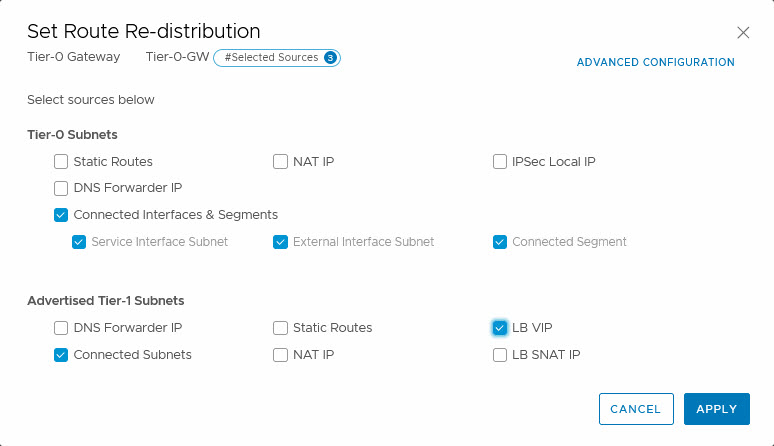
and add the LB VIP. Just a small check on one of the other tier-0 DR’s, to see if the route is distributed:
![]()
And then, trying out the load balanced web-page (pushing F5):

(just a small section of the page, but you get the gist…)
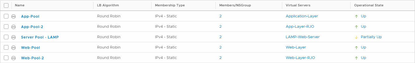
When powering of one of the web-servers, I can see the virtual server being partially available, within the Advanced Networking & Security dashboard:
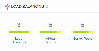
and when I select one of the items that is not fully green, I can get some extra details:
This is all within the Advanced Networking & Security part of NSX-T, I haven’t found a way of viewing this in the “new” interface yet.
The great part of the one-arm load balancer is that I can add a new web-server to it, put it on a totally different (but reachable) part of the network.
Next blog is about the inline load balancing (or two-arm as it is sometimes called).
4 thoughts on “Load Balancing with NSX-T – Part 1”
Correct me if I’m wrong, but isn’t this topology the Inline/2-arm LB?
Hi Anders,
Had to read it again, was some time ago that I built this and don’t have the environment available now to check, but I think it is a one-armed. I can imagine the confusion, since the second one of the visio-pictures (so excluding the pictures from the documentation) seems to show the load balancer as part of the Tier-1-GW, however, in the text and in the screenshots, you can see that it is another Tier-1, named Tier-1-LB. So routing is done by Tier-1-GW, and load balancing bij Tier-1-LB. Both are connected to the same T0.
I am going to play with load balancers in 3.0, so I will probably do a new blog on this (soon, I hope ;)).