Setting up layer-3 connectivity with NSX-T
After the installation (https://my-sddc.net/nsx-t-global-manager-installation-and-initial-setup/) and initial configuration (https://my-sddc.net/nsx-t-3-0-initial-configuration/), we can start building networks.
In order to get connectivity from the virtual network to the physical network, we need to setup layer-3 connectivity. In order to be able to do that, I bought a small Mikrotik device, to allow me to play around with BGP/BFD and VRF’s.
What we need to do to get layer-3 connectivity is:
- Create transport zones for transit networks
- Create an uplink profile for edge nodes
- Setup an edge node cluster (with two edge nodes)
- Setup a tier-0 gateway (T0) (with BGP to the physical world)
- Setup a tier-1 gateway (T1)
- Configure BGP routing
- Setup overlay-segments
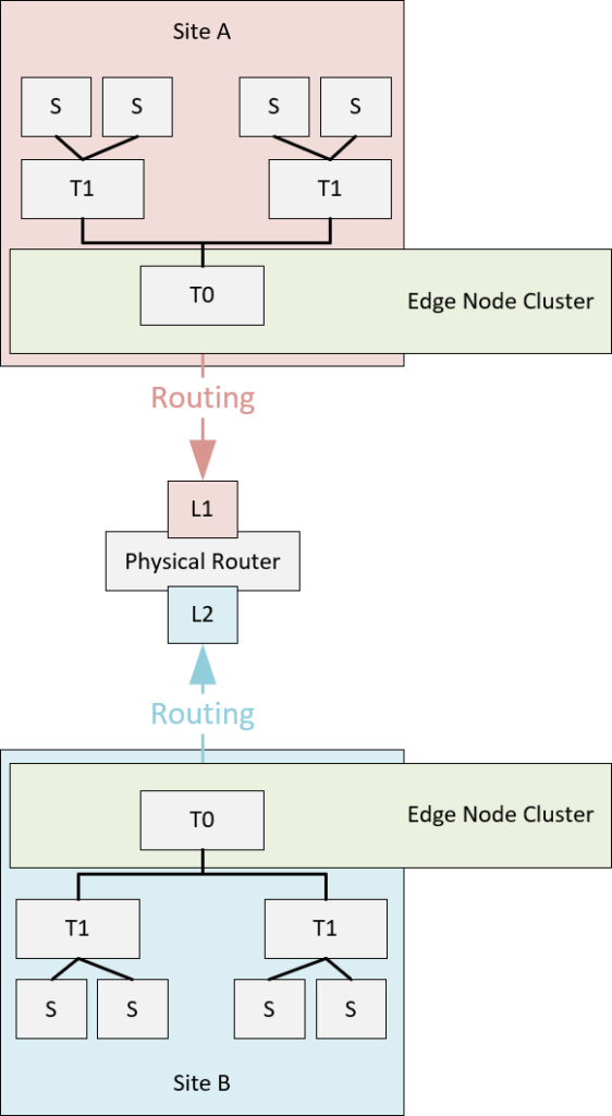
And we are going to do this on both Site A and Site B. After this we will have:
Create transport zones for transit networks
Transport zones are entities that define the boundaries of the segments that are created within them ánd give the means to separate segments, so they are not available everywhere. Only transport nodes (hosts or edges) to which a transport zone is connected (through an N-VDS or VDS), have the segments available within that transport zone.
Transport zones come in two flavors:
- Overlay
- VLAN
An overlay transport zone is used to create overlay segments (which means they are all software-based), and VLAN transport zones are used to create VLAN segments (duh!), which means the physical network should support the id’s that are used.
For a layer-3 configuration, we need transit networks to the physical network. This means using VLAN’s. Since those VLAN’s don’t need to exist on hosts, it is useful to create dedicated transport zones for them. One per transit network would be the preferred way. This way we can separate traffic and bind them to network interfaces on the edge node.
Creating a transport zone is very easy:
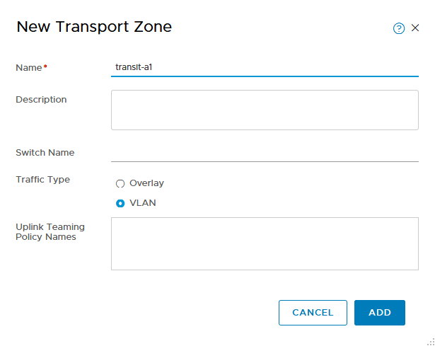
You can connect it to an already existing switch, but you don’t have to. For now this will suffice.
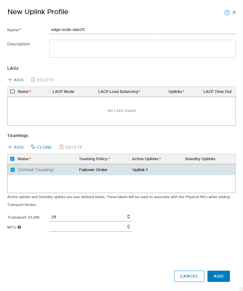
Create an uplink profile for edge nodes
We need an uplink profile for the edge nodes, because we need to specify the VLAN we are using for the overlay network (same as with the hosts).
Setup an Edge Node Cluster (ENC)
An Edge Node Cluster basically is a pool of resources on which to run virtual network functions. An edge node cluster is comprised of edge nodes (EN).
You might compare it to an ESXi host, which runs virtual machines. On an edge node, you run virtual networking functions. Clustering them gives the ability to increase resources ánd give high availability for the functions.
An ENC consists of one or more (maximum 8) EN’s and an EN can come in two forms:
- Physical
- Virtual
Since we are running a nested environment, we are definitely going the virtual path, but in production and even enterprise environments, the virtual edge node is usually the best way to go. For a physical edge node environment you must have some specific use cases.
Requirements like sub-second failover based on BFD could be one, lots of heavy layer-7 load balancing might be another. But we are not doing that here, so we are going virtual.
For our ENC we are going to create two edge nodes, on the underlay host. Placement of EN’s can be something to consider, since environments all differ, but it has some benefits not to mix them with workload environments. Since we have the ability to do that, we are going to deploy on the physical layer.
One thing to note here is that since we are creating an environment based on two vCenter Servers, we can’t add the vCenter Server from the underlay to one of the NSX Managers (because of the one-to-one relation of the connection), so we are going to deploy the EN’s and then bind them to the appropriate NSX Manager.
When you áre able to connect the vCenter Server to the NSX environment, deploying of an EN can be done through the GUI of NSX. For now, we deploy the template to the underlay.
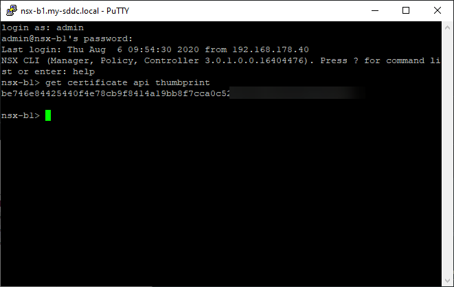
To prepare for this, we first need to download the OVA from the VMware site and secondly, we need to acquire the thumprint from the NSX Managers, to connect the EN to the Manager:
After we filled out all our information, we can deploy the virtual machine:

And do that four times in total, two per site.
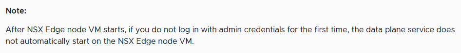
Important step to take, is log in with admin credentials on the EN, this will start the data plane:
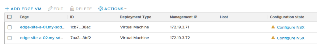
If the connection to the NSX Manager fails for some reason, you can manually connect it afterwards:

When the nodes are connected, it is time to configure NSX on them:
We are using four different kinds of networks on the edge nodes, so we will be using all four network interfaces.
- Management
- Transit-a
- Transit-b
- Overlay
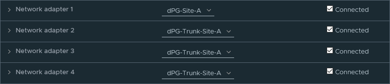
For the latter three, we need to create N-VDS’s (since edge nodes don’t use VDS’s like hosts). Those N-VDS’s need to be connected to the correct transport zones (already created) and on the physical level, be connected to the correct port groups, so the VLAN’s that are used, are viable here. While deploying the edge nodes, we connected the three interfaces that are going to be bound to N-VDS’s to the correct port group (Site-X-Trunk), which contains all VLAN’s for that site:
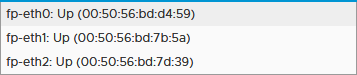
The first one is used for management (172.19.x.0) and doesn’t use an N-VDS. When we look at the mac-addresses of the other three:
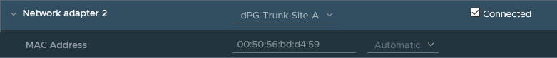


We can see that they are available in NSX as follows:
So when configuring NSX on the edge node, we create three N-VDS’s on it and connect them to the correct transport zones and network interfaces:
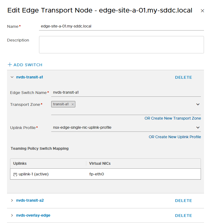
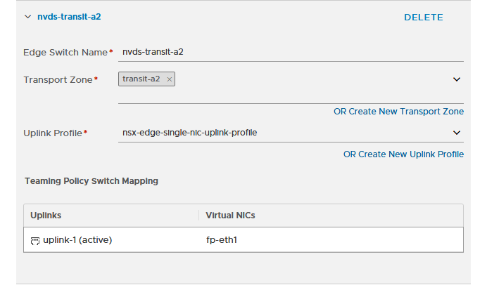
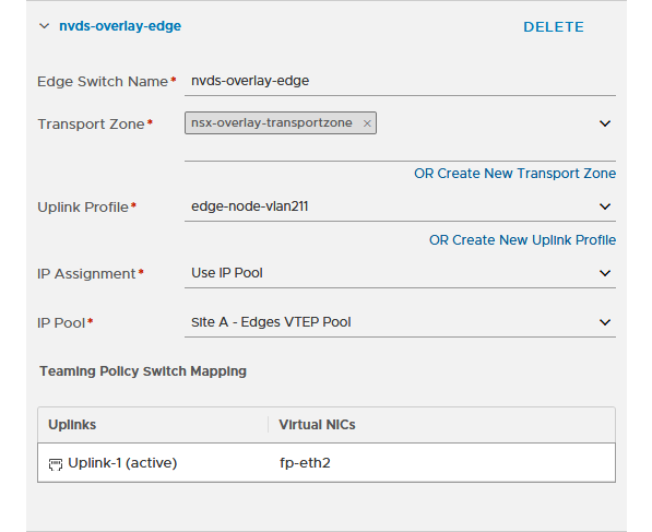
and of course, we do the same for all edge nodes. When we are finished, we can see all is green:
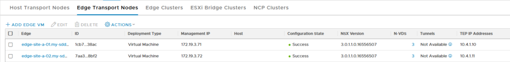
And we see that the VTEP-addresses have been assigned (we did need to create an IP Address Pool, like we did for the hosts, see previous post for that).
With two working edge nodes, we can create an Edge Node Cluster (ENC):

Setup a tier-0 gateway (T0)
Now that we have an edge node cluster, we can create a T0. This is the entity that will connect the virtual network to the physical network. In order to connect to that physical network, we first need to create two VLAN based transit segments, connected to the relevant transport zone:
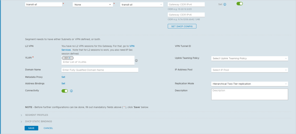
As you can see, when creating a segment, there are a lot of options we can fill out, however for this specific segment, just the name, transport zone and VLAN-ID will do. We do the same for the other transit networks and then we can create our first tier-0 gateway:
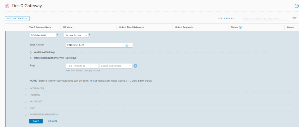
first step is the creation, after that is done, we can configure the T0 further. Create interfaces:
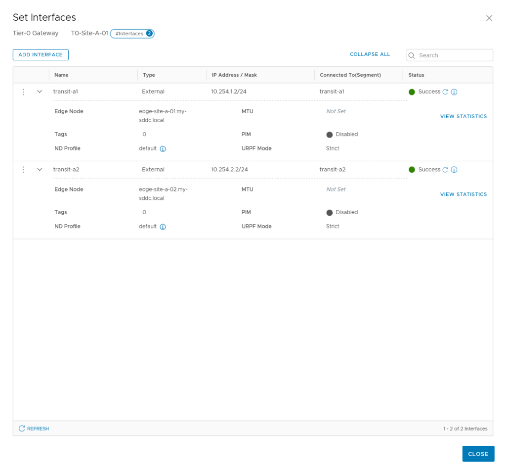
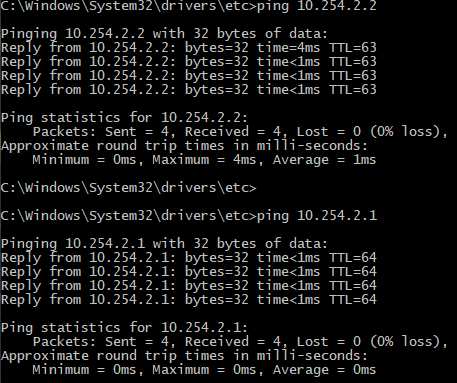
As we have also configured the physical side of this transit network, we can test if it is possible to reach the interfaces:
Setup a tier-1 gateway (T1)
It is possible to connect segments directly to a T0, but since we are using multi-tiered routing, we want to create and connect a T1 gateway. Creating this is very easy, since there is no need to configure any routing protocol, this is all done automatically by connecting it to a T0:
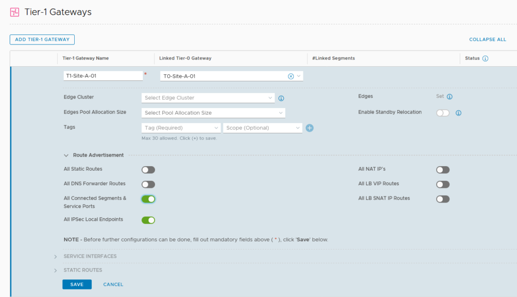
We do not connect the T1 to an edge node cluster, because if we do, routing will always flow through the edge node. If we only want “normal” routing, we can do that all in a distributed manner. See https://my-sddc.net/distributed-multi-tier-routing-in-nsx-t for an explanation on this.
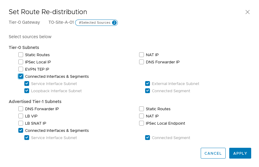
We dó select the correct Route Advertisements. This is what is sent upstream to the T0, and gets advertised to the physical layer. In our case, we are doing routing through this T1, so advertising the segments will be sufficient.
Configure BGP routing
In order to advertise the segments we are deploying to the physical layer, we can use two methods:
- Static
- Dynamic
Static routing could be useful if there is one block that is living in the virtual world and you don’t want the hassle with setting up dynamic routing. If you want to set it up this way, you would normally run in an Active/Standby mode, where one interface, with one IP-address can be made redundant over two or more edge nodes.
We are using ECMP (Equal Cost Multi Pathing) as both a means of redundancy and load balancing of traffic and in order to use ECMP we do not dynamic routing, to be able to detect the failure of one of the paths.
So the dynamic routing protocol within NSX-T 3.0 is still only BGP. Maybe OSPF will come in the future, but BGP is perfectly fine for us.
For BGP we setup the physical router to AS 65030 (it has that by default), the NSX environment for Site A will be 65010 and Site B will be 65020.
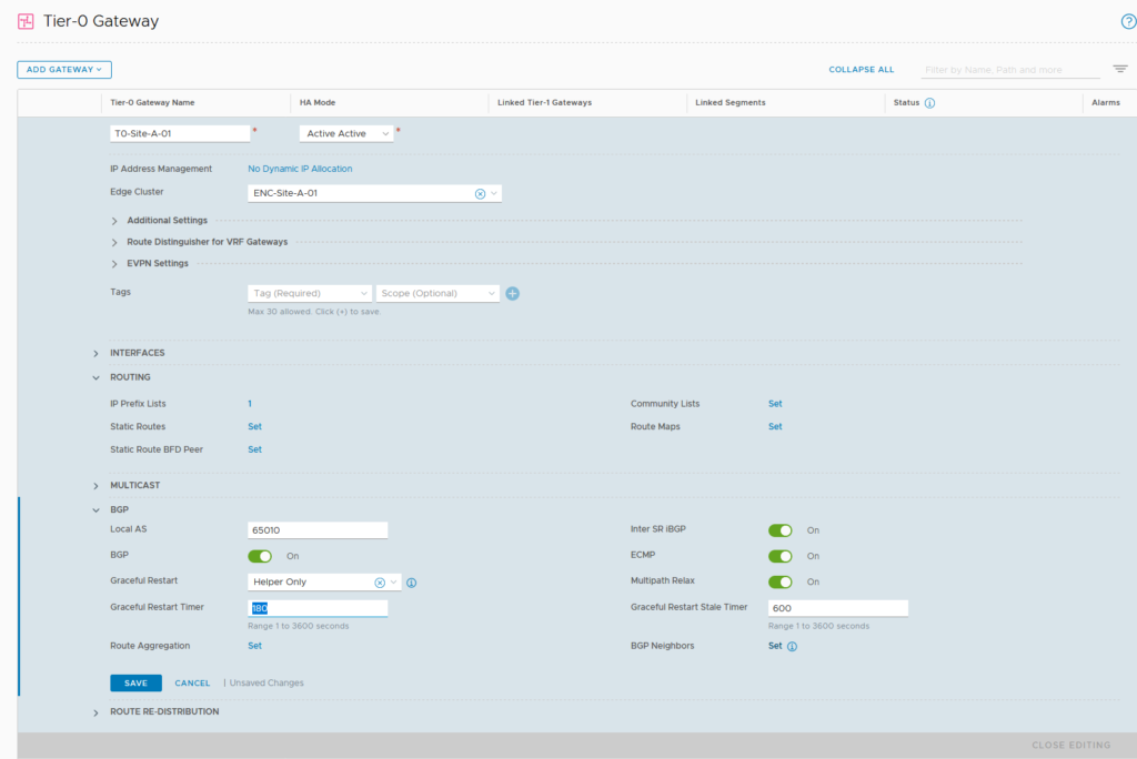
BGP is enabled by default, with AS 65000, we change that to 65010 and after we have done that, we configure our BGP Neighbors, by clicking “Set”.
Since we have two transit VLAN’s with different IP-subnets, we connect to the physical world over both. Therefor we need two neighbors:
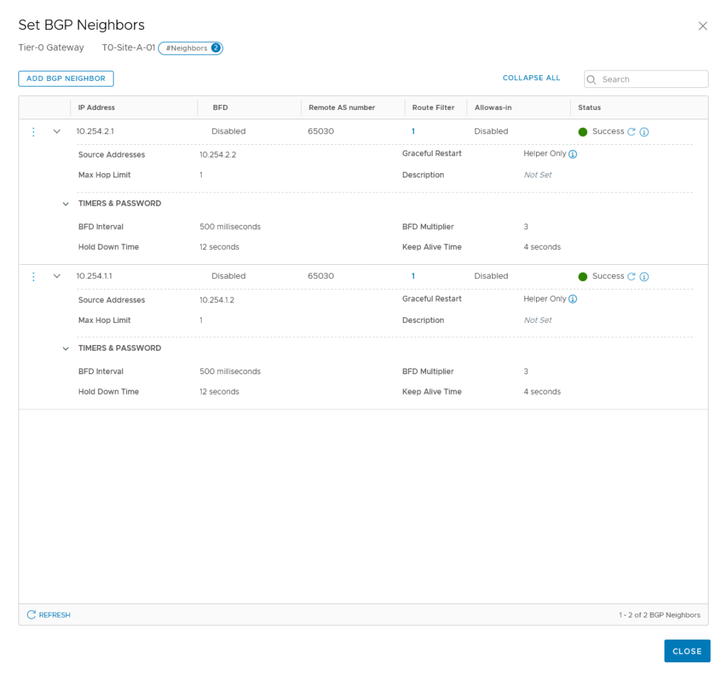
For now, we don’t do BFD, but we will come back to that later. The peering has been successful, so we can go and tell it which routes to advertise:
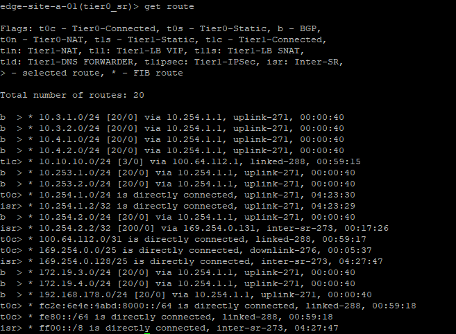
When we look at our own routing table, we see that the physical world is telling us which networks are available (and that we learned that through BGP):
Setup overlay-segments
So we can now finally create our new layer-2 networks, connect them to our T1 and have connectivity to the rest of the world. This step is pretty easy, after all other steps have been taken:
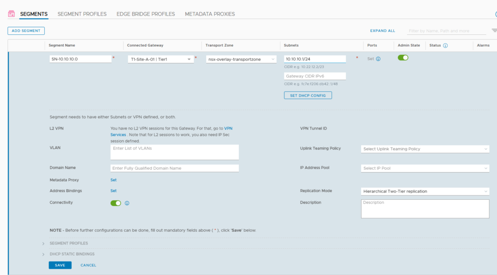
Again, a lot we can fill out, but just a name, a connection to at T1 (or T0 or to nothing, if it doesn’t need to talk to the outside world) and the correct transport zone.
After creating the segment, we can see it in vCenter:
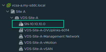
And it’s distinguishable from the other networks, because of the little N.
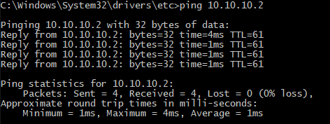
When we connect a virtual machine to the network and give it the correct IP configuration, we can talk to the outside world (and vice versa):

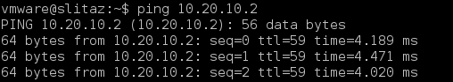
And the virtual machines, in different NSX environment, can also reach other, through the wonders of BGP:
One thought on “Setting up layer-3 connectivity with NSX-T”