Holodeck Lab: Multi-Tenancy routing with VRF’s in NSX
The Holodeck Lab is up and running and some of the components have been replaced by pfSense. This has been described in a couple of blogs. Now it’s time to start working on the use cases I wanted to explore with this lab. The first one is doing Multi Tenancy with VRFs within NSX.
Firstly, the topology I am planning to implement:
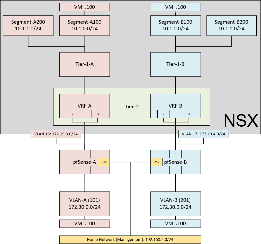
If you look carefully, I am planning to create two distinctly different network topologies, within the same NSX environment. The goal is to be able to have overlapping IP-schemes both within and outside of NSX. This would allow one of our customers to support several of their customers each with their own ip-address-scheme, which could overlap with other customers.
Through the use of VRF Lite, I should be able to build what I have designed in this picture.
I am going through the following steps:
- Deploy pfSense Appliances
- Configure BGP on pfSense
- Configure BGP on NSX
- Create Distributed Port Groups for the VLAN’s
- Create VM’s to test the setup
- Test Connectivity between VM’s
So first off, I deploy the pfSense appliances. Two of them and both are going to be running on the underlay server.
How to install a pfSense is described in this blog: Holodeck Lab: Replacing Networking with pfSense – My Software Defined DataCenter, with a few small adjustments:
- Two network adapters,
- One connected to DPG-Home (for Management purposes only) and
- One connected to DPG-VLC-A
(this will be used to create two VLAN interfaces, one on the interconnect VLAN 16 (A) or 17 (B) and one on the “Tenant VM” VLAN (101 (A) or 201 (B), see above).
Deployed it once, and cloned after installation was completed.
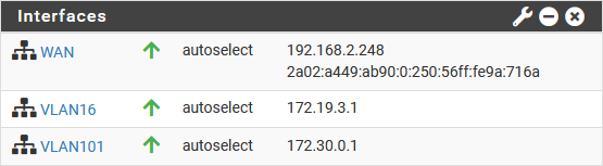
After deployment, I created the VLAN-interfaces, with addresses as shown in the picture and I disabled the Firewall functionality altogether.
This leads to the following configuration, from both pfSense appliances:
A:
B:
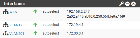
Note that the subnets for VLAN101 and VLAN201 are the same, to mimic an overlapping IP-address scheme within different customer environments.
Configuration of BGP Routing on pfSense
Next up is installing FRR/BGP, from System | Package Manager, and after that has been completed, configure the pfSense side of the BGP configuration. For this, I am configuring the following screens:
Services | FRR | Global Settings:
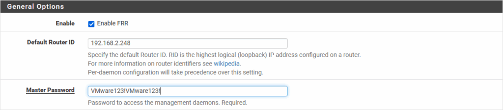
(For the other pfSense-B, the Router ID will be 192.168.2.247)
Services | FRR | Global Settings | Edit | Prefix Lists:

Services | FRR | Global Settings | Edit | Route Maps:

Services | FRR | BGP | BGP:
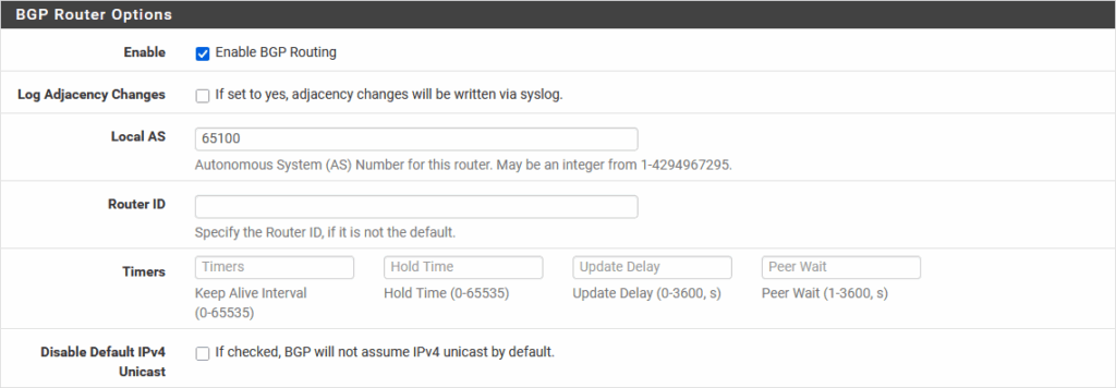
(for pfSense-B, Local AS is 65200)
Services | FRR | BGP | Edit | Neigbors:
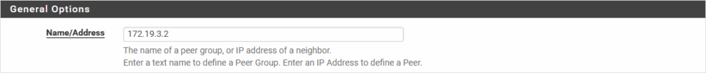


(Name/Address for pfSense-B: 172.19.4.2 | Remote AS for pfSense-B: 65201).
We also create a second neighbor for both pfSenses, with the last octet being .3, for the second interface on NSX (which we will be creating later on).
That concludes the configuration on the pfSense side. Next up, NSX.
Configuration of BGP Routing on NSX
Here we are creating two VRF’s, with almost identical configuration, so again, showing what I have done for the left side of the picture and mentioning the differences for the right side.
First, we create the necessary Interconnect Segments (VLAN16 and VLAN17), to connect the VRF’s to the pfSenses:
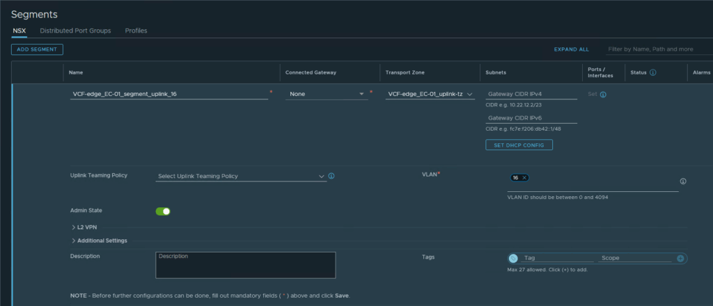
Connected to the (already existing) Transport Zone “VCF-edge_EC-01_uplink-tz”. This will make sure these VLAN’s will be propagated to the Edge Nodes (and not to the Hosts).
Same for VLAN 17.
Add a VRF:
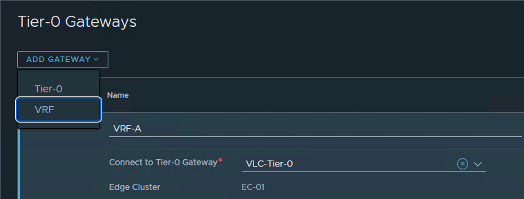
And continue configuring, when asked the question. We will configure two interfaces on this VRF, with the following specs:
- Name: Interconnect Interface-1 – VLAN 16 (Tenant A)
- IP Address: 172.19.3.2/24
- Connected to: VCF-edge_EC-01_segment_uplink_16
- Edge Node: edge1-mgmt
and
- Name: Interconnect Interface-2 – VLAN 16 (Tenant A)
- IP Address: 172.19.3.3/24
- Connected to: VCF-edge_EC-01_segment_uplink_16
- Edge Node: edge2-mgmt
For Tenant B, we use:
- Name: Interconnect Interface-1 – VLAN 17 (Tenant B)
- IP Address: 172.19.4.2/24
- Connected to: VCF-edge_EC-01_segment_uplink_17
- Edge Node: edge1-mgmt
and
- Name: Interconnect Interface-2 – VLAN 17 (Tenant B)
- IP Address: 172.19.4.3/24
- Connected to: VCF-edge_EC-01_segment_uplink_17
- Edge Node: edge2-mgmt
After completing this, it would be good to test connectivity to the pfSense, by using “Diagnostics | Ping” on the latter:

Then, we create the BGP connection between the VRF and the pfSense for Tenant-A:
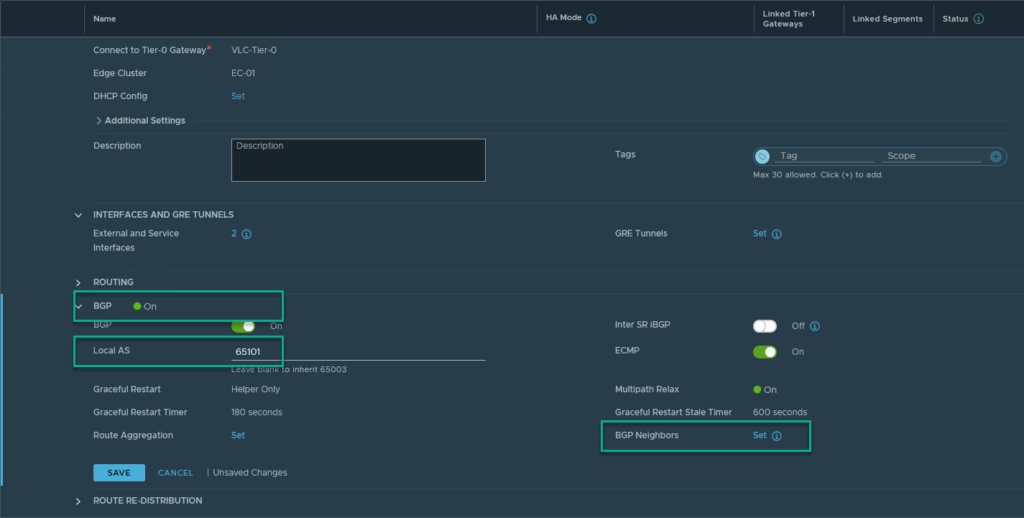
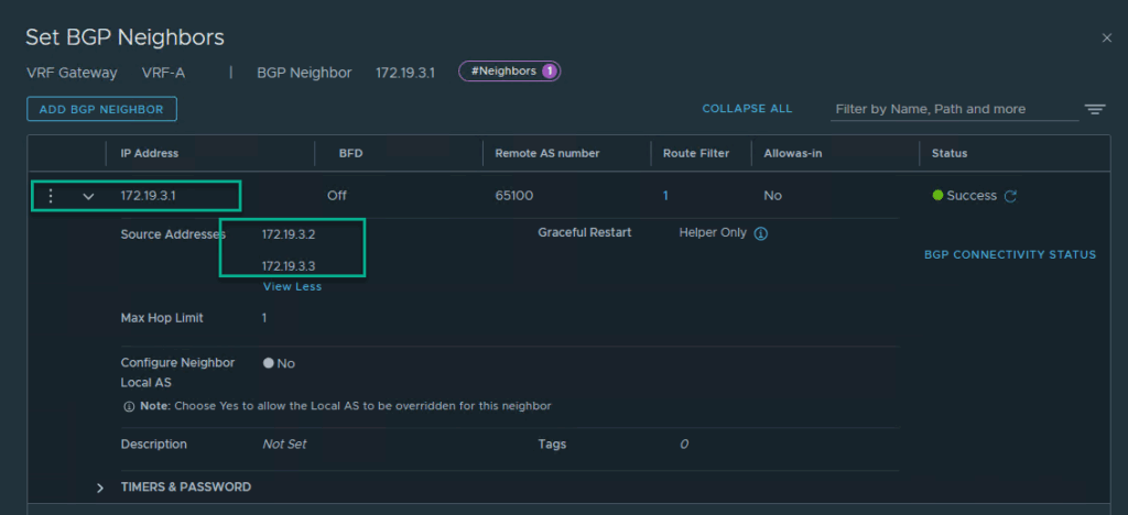
Enable BGP, Fill in the Local AS (for Tenant-A, this is 65101) and configure the BGP Neigbors by clicking on “set”.
(For Tenant-B we use 65201)
We create one neighbor, but we use the two Source Addresses we created in the previous step (one active on Edge-1, the other on Edge-2):
Lastly, on this page, we have to configure “Route Re-Distribution”, when we open this menu, we can click “set”, just under Route Re-Distribution, and add a new entry, with (for instance) the following setting:
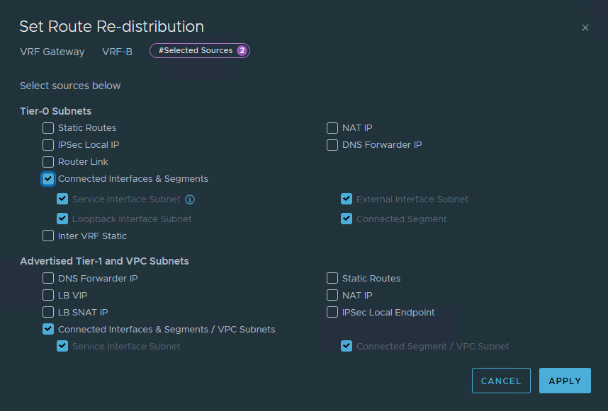
In our case, we only want to distribute the subnets for the Segments that we connect to the Tier-1 we are going to create later on and the connected interfaces & Segments for the VRF itself.
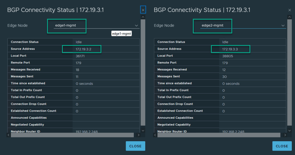
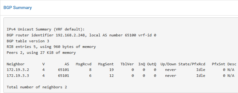
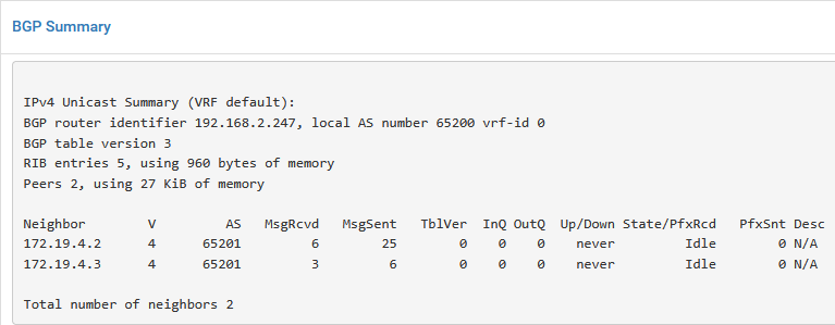
After this is filled in, we can see the BGP status being active, both on NSX:
and on the pfSense:
We repeat the above, for Tenant B, leading to:
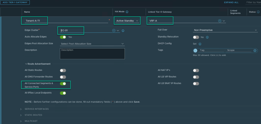
To get a real feel for the real world, we now create a T1 for both Tenants, connected to their own VRF:
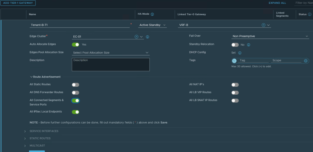
And two segments connected to the newly created T1. We use the same IP-addresses for both Tenant-A and for Tenant-B:
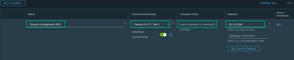

(same for Segment-200: 10.1.1.0/24 to get the picture we were after)
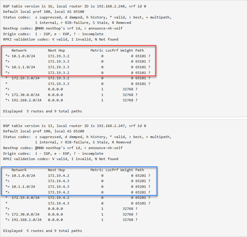
And now we can see the route becoming available on both pfSense appliances:
Create Distributed Port Groups for the VLAN’s
I have created DPG-VLAN101 and DPG-VLAN201 on my distributed switch, with the corresponding VLAN-ID, to connect them to the pfSense, where the same VLAN-ID’s were used during the initial setup.
Create VM’s to test the setup
Last step is create VM’s on both sides of this routing configuration. So four VM’s in total:

With the following IP-addresses (same for both tenants):
Tenant-X-Segment-100: 10.1.0.100
Tenant-X-VLAN-101: 172.30.0.100
Test Connectivity between VM’s
When we trace traffic for both Tenant A and Tenant B, for both from Segment to VLAN and vice versa, we see that the 172.19.3.0/24 subnet is used for connecting Tenant A and traffic for Tenant B flows through the 172.19.4.0/24 subnet, just as we see in the original picture. Even though the IP-addresses for both sets of VM’s are identical.
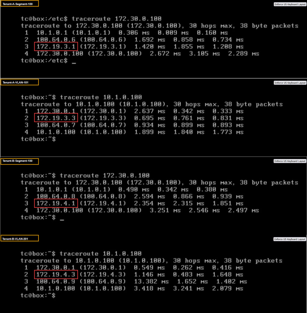
And so there we are, two customers living on the same NSX based environment, with identical IP address schemes.
One thought on “Holodeck Lab: Multi-Tenancy routing with VRF’s in NSX”